
Introduction
OSI stands for Open Systems Interconnection. It is a model that helps as the reference for Networking and was developed in 1984 by ISO. It provides a high-level overview that how to transfer data from one host to another host.
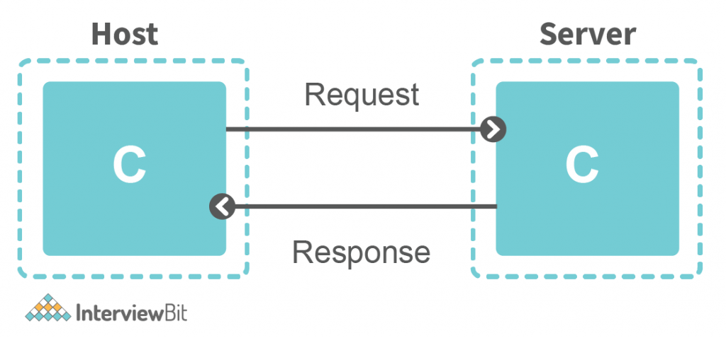
- Anything which is a part of the network which wants to communicate is called a Host.
- The server is a special type of computer. It is also a Host when receiving data from clients. The server is something that a host receives data.
- OSI Model is finalized between the 1970s and 1980s. And it is a reference model, which means, It acts as a reference guide to implement or form the network in the real world.
- Based on the OSI model, the exact model that is implemented in the real world is TCP/IP model.
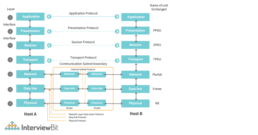
- OSI Model has 7 different layers. And each layer has a bunch of protocols that need to be followed to implement a network in the real world.
- Protocols – A set of rules that everyone needs to be agreed upon.
The network can be defined as the collection of interconnected computers usually we call it the Host which is communicating with ear other to share data.
Networking is the process of creating a network based on protocols, hardware, software, mediums, etc and the data flow of data between devices in the network.
Confused about your next job?
What is OSI Model
OSI Model follows the approach of a Layered system. That is something the researchers came up with while developing the OSI Model. OSI Model is based on the architecture called Philosopher translator Secratory Architecture.
In this architecture, there are two philosophers (A and B) in different locations and they don’t know the same languages and want to transmit a message. So some steps need to be followed by both to successfully send the message.
- Philosopher A gives the message to his secretary and the secretory will convert the message into a common language that can be understood by the secretary in both locations.
- Then the converted message will be sent through Fax to Location B. And the secretary in location B will understand the message and pass it to the philosopher in the language the philosopher understands.
So this way communication happens in this architecture. So the same is followed in the OSI Model. Each layer states the different protocols that need to be followed for the successful transmission of the message.
Characteristics of the OSI Model
OSI model is divided into 2 different groups. One group is the responsibility of the Host and Another one is the responsibility of the Network.
The layers that come under the responsibility of the Host are –
- Application Layer
- Presentation Layer
- Session layer
- Transport Layer
And the layers that come under the responsibility of the Network are –
- Network Layer
- Data Link Layer
- Physical Layer
The responsibilities of the hosts are – Encryption, Session Management, Segmentation, Flow control, etc.
And, the responsibilities of the network are like – path to router packet, congestion control, Network identification, etc.
OSI Model Layers: 7 Layers of OSI Model
OSI Model has seven different layers that we have already discussed in the characteristics of the OSI Model. Now let’s understand a more zoomed view of these layers –
1. Application Layer
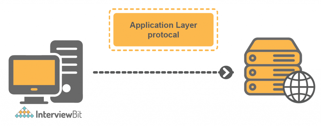
This layer deals with the application part. Applications that require communication with the network, then the protocols defined in the application layer will be followed by the applications for transmission of data.
The Application Layer contains a bunch of protocols. The protocols are like this –
- Browser —- HTTP / HTTPS, FTP
- Outlook —- SMTP
- Skype —- Skype Protocol
- Remote Desktop —- Telnet, RDP.
These are all the software that runs on the client side. And have a set of protocols that are followed by the application based on its functionality for communication.
- HTTP – (Hypertext Transfer Protocol) is a protocol that is used to transmit web pages, images, text over the internet from a browser.
- HTTPS – It is the secure version of HTTP. It says, securely transmits the data over the internet. Ex – password, card details, etc.
- FTP – (File Transfer Protocol) is used when we want to transfer a file from one computer to another computer.
- SMTP – (Simple Mail Transfer Protocol) is used to send and receive emails over the internet.
All these are open protocols that every browser uses to transfer data over the network. While some are proprietary protocols like – Skype Protocol which only skype uses. And also (RDP) Remote Desktop PC, which only Microsoft.
So Application layer is a collection of protocols and based on the application, we use the appropriate protocols.

Explanation – In the above figure, the Client communicates with the server. Here is the mail server, that operates on the application layer to handle the mail request from the client/host.
2. Presentation Layer
The presentation layer is responsible for broadly 3 tasks –
- Translation – It translates the data received from the application layer into the form of ASCII (American Standard Code for Information Interchange) Codes, or UNICODE to the Binary Format.
- Example – Data – Hello. So ASCII Code associated with it is 72 101 108 108 111. And the next to the Binary Code will be – 01001000 01100101 01101100 01101100 01101111.
- So this is the first thing that the presentation layer will do post receiving data from the application layer.
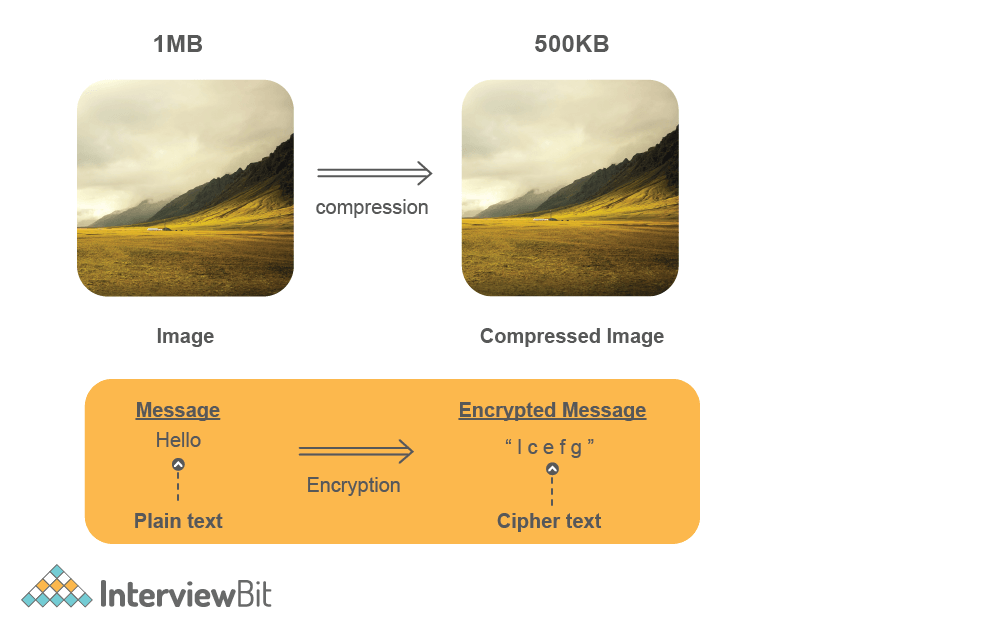
- Data Compression – In this what exactly happens is, Suppose after translation we get 1MB of Data. So Data Compression tries to reduce the size of the data without much loss of data because the less the size is the faster transmission can happen over the network.
- Example – Suppose we have an image of size 1MB, Now Data Compression tries to reduce this file size to less than 1MB.
- So this is also done by the Presentation Layer for better communication.
- Encryption – The objective of encryption is to encrypt the data so that the data can’t be understood by hackers that might see the data and misuse it. HTTPS uses SSL (Secure Socket Layer) protocols to encrypt the data. Secure Sockets Layer is a cryptographic protocol designed to provide communications security over a computer network.
- Example – Suppose we want to transmit the password or any confidential data, then sending a plain text might not be secure. So presentation layer also secures this information by encryption and sends it over the network.
- In the above image we can see that compression reduces the size of the image and the Message (Plain Text) is encrypted into the Encrypted text (Cipher Text). These are all done by the presentation layer.
3. Session Layer
Session Layer manages the session management of the network connection. It does a bunch of things –
- Establish, Manage and Terminate Connection –
- Establishment of Connection means making a connection in which both server and client have agreed to transfer the data.
- Managing Connection states getting knowledge of the connections which was established and the data transfer can be done effectively.
- In Terminating the connection, after the data transfer completes then the connection must be terminated.
- Authorization and Authentication –
- Authorization states valid user id or password or not. Authorization states after the authentication, whether the user has permission to access the particular file or not.
- Example –
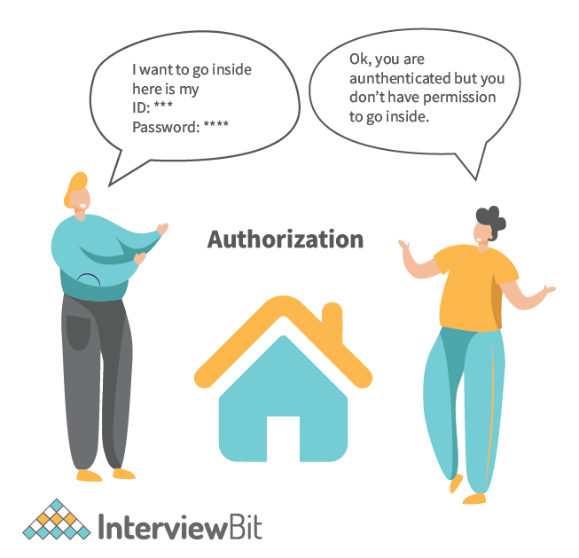

- Explanation –
- In the above images, The person wants to enter the office then the security personnel will ask the person to authenticate himself. The person provides the User Id and password to authenticate. So this is called authentication. To check whether the person is the right person or not.
- On the other image after authentication, the security personnel will verify whether the person has the authority to go inside or not. If it has authority then the person can go. Otherwise don’t.
- So the same approach is followed in the session layer of the OSI Model, which also helps to authenticate and check authorization to allow access.
Most modern browsers take care of all the 3 layers: Application, Presentation, and Session. Browsers are like – Chrome, Firefox, etc.
4. Transport Layer
The transport layer manages whatever data comes from the above top layer, It performs something called –
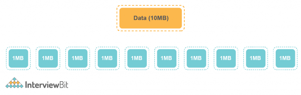
- Segmentation – Segments are the small groups of data that are divided from the large data. Suppose we have 10 MB of data then the whole 10MB data is divided into segments supposing 1MB each.
Why Segmentation? – The big question arrives is why the data is divided into segments. Why can’t the whole lot is being sent on a go?
- It is because the protocols that are used in the Transport layer like (TCP, UDP), Each has different sizes of segments.
- Segmentation does that if the data is divided into pieces, then it is more manageable.
- Each segment must be given a number because, in transportation, It may not the situation that the segment arrives in the same sequence.
- On the other end in Transport Layer, If a segment has a number then it will be easy to send the data over the medium.
- Each Segment contains the port number that needs to identify the hat software did access this data that is sent to the network.
- A general segment looks like –
- A browser typically uses Port no 80 for HTTP Requests.
2. Flow Control – Flow control means managing the flow of data that is transmitted between one host to another host.
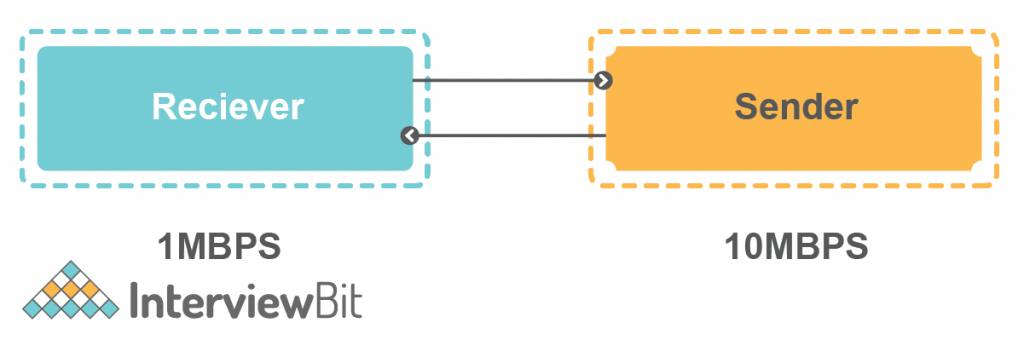
- Suppose Sender is sending data to Reciever @10MBPS Transfer Rate. But the receiver can’t able to process the data @10MBPS. It can only process data @1MBPS.
- So the receiver will ask the server for a 1MBPS Transfer rate, As it can’t process the data. Then sender sends the data @1MBPS Rate.
- So this is called Flow Control.
3. Error Control – It controls the error of data. This means in case there is any inconsistency happened on the data then it helps to correct that data.
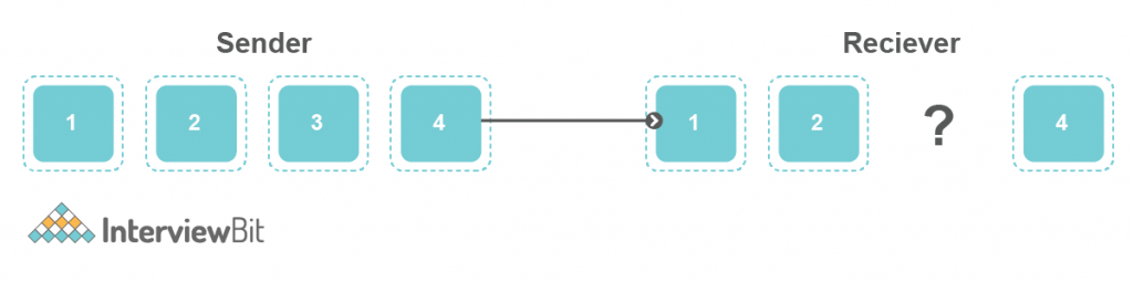
- Suppose Sender is sending some data considering 4 segments. Now in case, the 3rd segment got lost in the medium. So Error control helps to fix that.
- It has some algorithms that help to fix this data. Like Automatic Repeat Request. In which the segment hasn’t receiver to the receiver. Then it will ask to resend it.
- Data loss can happen in the physical network, So errors are recognized and controlled by the transport layer.
- Other than these general things, the Transport layer also performs the merging of the data in the packet which is received from the Network layer. And it merges according to the sequence number.
- And then it sends the data to the above layer to the particular application it has been associated with. Using the port number.
5. Network Layer
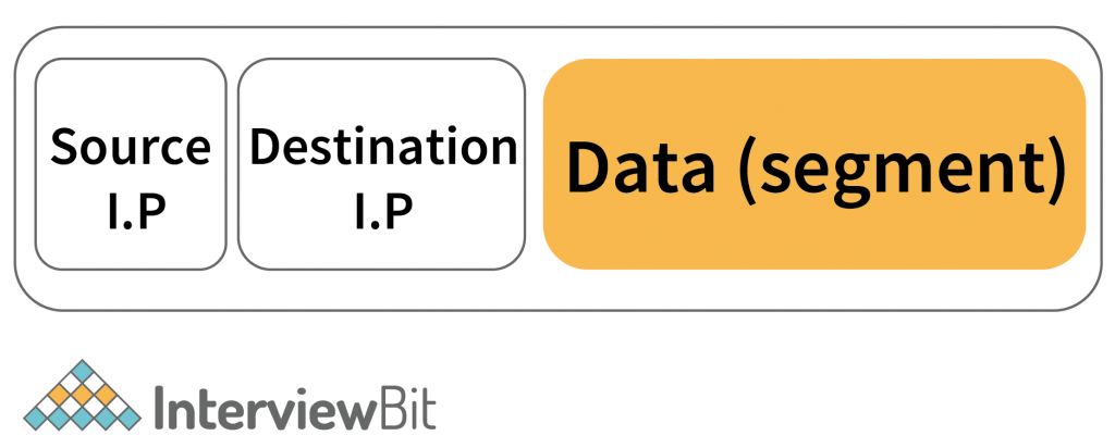
The network layer’s main task is to recognize the network in which the data has to be transmitted. It has something called a packet. And Packets is made up of the data received from the above layer. Is encapsulated with the Headers in which the source and Destination IP address is mentioned.
After encapsulating the segment with the source and destination I.P. Address. It generates the packet. So the general packet looks like this –

What is IP Address?
- It is the address that the network system has uniquely identified. It is the 32-bit or 4-byte address (in IPv4) and each byte has an address range of 0-255, called an octet.
- So the task of the network layer is to provide the IP Address to each host. And it also does something called Routing.
What is Routing?
- Routing means setting the path of the packet to reach from the sender to the receiver.
- Explanation:
How do Routers do that?
- The router does this, When a router gets the destination IP address and then performs something called masking.
What is Masking?
- Masking is a simple bitwise operation. The router sets some bits to 0 and performs a bitwise AND operation, and after masking on the destination IP address, it will get the network IP Address.
- Now with the help of the network IP address, it will decide the next router for the packet it has to send.
How does the network layer encapsulate the packet with the IP Address?
- There is something called DNS. Domain Name System, that provides the IP address corresponding to the domain name it has been requested for.
Path Determination –
- What it means is actually that, there could be multiple ways from which I can send one packet to the destination. The objective of path determination is to determine the best path so that I can send this packet very very efficiently in less time.
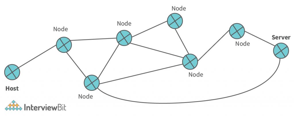
- So here in the above figure, we have multiple nodes from the host to the server. So routers help to determine the path that needs to be followed so the packet reaches the destination efficiently.
- So routers use algorithms used in graph theory, like minimum spanning tree, shortest path, etc.
Other than this, While receiving the data the network layer also checks for the data it received from the (Data-link Layer). It extracts the data from the header and sends that to the above layer (usually to the host part) [Transport Layer].
6. Data-Link Layer
The packet which is sent from the Network layer, And on that packet the headers are added along with the MAC Address of Source and Destination.
- MAC Address – (Media Access Control) is the 48-bit or 6-Bytes long containing the Hexadecimal code. It is the address assigned uniquely to each of the network devices.
- MAC address is also called physical address because it contains the address of the physical network device from which data is going to be transmitted.
- It is assigned to the network devices such as NIC(Network Interface Card) WiFi Card, USB WiFi Dongle, etc. by the manufacturer.
After encapsulating the packet from the network layer with the Source and Destination MAC Adress. Data-Link Layer generates a Frame. And that frame is sent to the next layer for data to send to the destination. A general frame looks like –

Why MAC Address? MAC address helps to uniquely identify the device. Suppose in the network, the packet is received, then which particular device belongs to. So the MAC address helps to identify this.
Other than this, Data-Link Layer also have some broadcast –
1.Access to Media – Media are like – (Copper Wire, Fiber Optical Cable, Wireless), etc. So the data link layer has access to these media such that it can detect congestion, Error, Collision, etc.
2. Media Access Contol – It also helps to control the medium such that when to transmit the data.
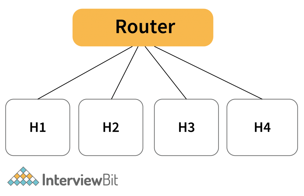
- In the above figure. Multiple Host is connected to the same router. Now if all the hosts send the packet to the router then it will be a collision.
- Not all are allowed to send packets at the same time.
- So what Media Access Control does is that It checks for the medium (wired or wireless) whether it is free or not. If it is free then the particular host will send data to the router else the host will have to wait.
3. Error Detection – It is the mechanism to detect any error on the data. This means checking whether the data is correctly received or not.
Some algorithms help to check that. Like – CRC (Cyclic redundancy check), Checksum, Bit Parity, etc.
- These all are 3 activities stated above are the general thing that the Data Link layer does. Now on the time of receiving the data in the form of a Stream of bits from the physical layer. It checks for the header and identifies the MAC address that does belong to the same device or not.
- If it belongs to the same device then It extracts the data part from the Frame and sends it to the above layer (Network Layer).
7. Physical Layer
- The Data Link layer gives a frame. And that frame needs to be transmitted to the destination. And the data are in the form of bits. So physical layer converts that data into an appropriate signal and transmits the data.
- Physical Layer also deals with the encoding of the stream of bits into the signals. The appropriate signal can be said to be the data into the form of an electrical pulse or laser beam, etc.
- These signals are categorized based on the type of medium. Like for Wireless – A Radiofrequency is there in which the data is in the form of a frequency wave. Other in Wired – Optical Fiber Cable – Data will be the form of laser beam etc.
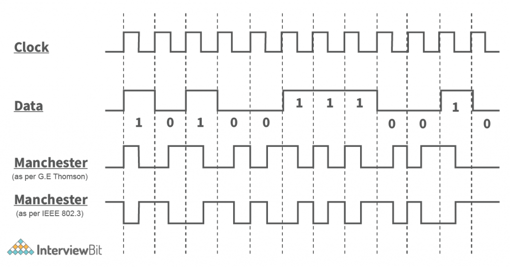
- There are many encoding schemes in which the data is encoded. Like – Manchester Encoding (As per G.E. Thomson and also IEEE 802.3 Encoding Scheme), Differential Manchester Encoding Scheme. Etc
- Other, on the receiver side, the physical layer accepts the electrical signal that is received, Decodes that signal and makes to a stream of bits, and sends it to the upper layer (Data Link Layer).
Explanation – In the below image, Data is encoded into the manchester encoding form according to the clock pulse.
Conclusion
OSI Model is the basic model that acts as the reference model for the implementation of the network or designing of the network in the real world.
There is the same model that is implemented in the real world called TCP/IP model with the layers stated in the OSI model. In this, various algorithms help in the transmission of data from a host to the destination.