- What is a Network?
- What is Transmission Media?
- What is the Type of Computer Network?
- Network Topology and its Types?
- 1. Bus Topology
- 2. Ring Topology
- Protocols Used for Data Transmission in Ring Topology:
- Advantages of Ring Topology:
- Disadvantages of Ring Topology:
- 3. Star Topology
- What is used as the central station HUB/SWITCH?
- Protocols used in Star Topology:
- Advantages of Star Topology:
- Disadvantages of Star Topology:
- 4. Mesh Topology
- 5. Tree Topology
- 6. Hybrid Topology
- Conclusion
Network Topology states how different types of computers can be connected to the network. There are different types of networks, and implementing this network with the help of the transmission media is done with the help of network topologies.
What is a Network?
A network is a group of computers that are connected through the transmission medium to communicate between them and exchange information or data.
What is Transmission Media?
Transmission media is the medium that helps to connect different network devices. It can be wired or wireless. For Example – Mobile phones are connected to the mobile tower, here wireless transmission media is used. And similarly, we use a fibre internet connection, that is wired transmission media.
What is the Type of Computer Network?
Various types of networks are formed with the help of network devices and transmission media. And these networks are called with different names according to the size of the network. Some of the types of computer networks are –
- PAN (Personal Area Network).
- LAN (Local Area Network).
- CAN (Campus Area Network).
- MAN (Metropolitan Area Network).
- WAN (Wide Area Network).
Understanding these types of network types is itself a large topic. Let’s focus more on what are the different types of network topology.
Network Topology and its Types?
Network topologies are how computers connect and relate to one another in the computer network. And there are two types of topology in computer networks-
- Physical Network Topology.
- Logical Network Topology.
Physical Network Topology – It describes the way these networking devices are connected with the help of cables.

Each computer or Networking device connected to the network is called a Node. And the physical network topology describes the physical layout of the nodes available in the network.
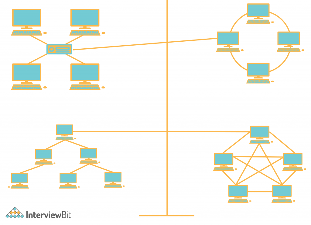
The most common computer network used to interconnect physically distributed computers (networking devices) is LAN (Local Area Network). LAN is a privately owned computer network that operates in the short-span area usually in the building. And this has four main topologies –
- Bus Topology.
- Star Topology.
- Ring Topology.
- Mesh topology.
With these main topologies, others can also be derived like- Tree Topology and Hybrid Topology.
Logical Network Topology – It describes the set of protocols that were used to transfer data or information between the nodes in the network. It is related to the transfer of data between nodes.

Now let’s see the details of each of these different types of network topologies. And while studying each of the physical network topologies, we will also see the logical flow of the data that happens between these topologies-
1. Bus Topology
In a Bus Topology, all nodes are connected to a shared central cable called Bus. And these nodes are connected to the Taps and Drop Lines through the bus. In this, Drop Lines are simply the connection between the central wire or bus with the nodes. And the Taps are the 3-way connector. That helps to attach the drop line to the main central cable. Bus Topology is a very popular topology. Most ethernet LANs use a bus topology.

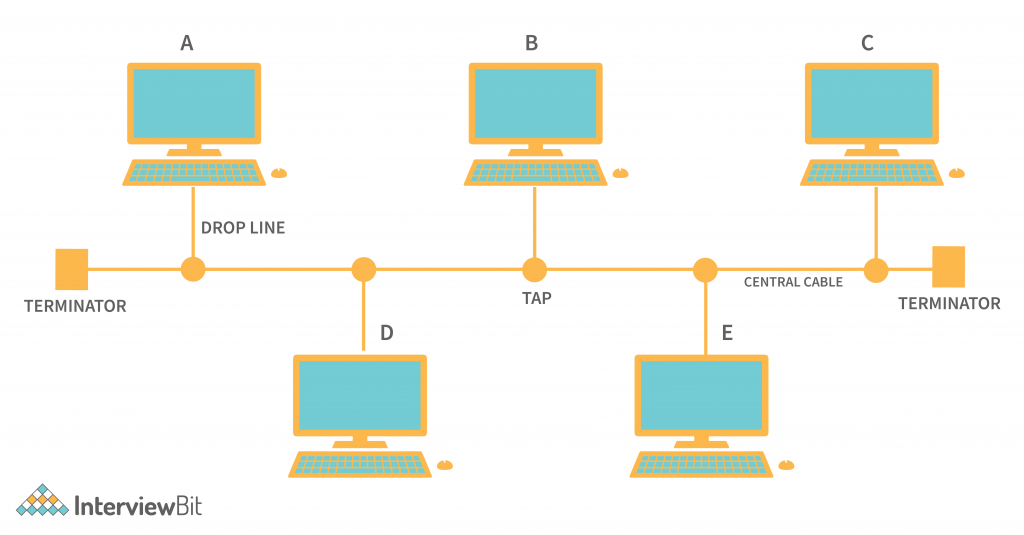
In the above figure, we can see that each node is connected with the central shared wire with the help of the Taps and Drop Lines.
In this network topology, suppose node A wants to send a data frame to Node E then it can use the Shared wire. And as well as if Node C wants to send data to Node D then it can also use the same shared cable. So if any node is sending data to other nodes, then because of this common shared bus, the data is received by all of the nodes connected on the bus. And the destination node will accept the data frame. And others will simply reject that. This identifies because of the destination MAC Address provided in the data frame.
Protocols used in Bus Topology:
Suppose Node A wants to send data to Node E and at the same time Node C wants to send data to Node D. And they both are sending the data simultaneously. Then the data will collide and be corrupted. So there must be a mechanism that can help to avoid these issues. And various (Media Access Control) protocols are followed by the LAN Ethernet connection Like CDMA, TDMA, Pure Aloha, Slotted Aloha, etc. These all are a set of protocols that are mostly used in LAN Protocol following bus topology connection.
Advantages of Bus Topology:
- Less Cabling – Bus topology uses a common wire to all the nodes. So it is less expensive. And because it is less expensive, it becomes easy to install and also it is less expensive.
- Small Network – This is best suitable for a place where there are small numbers of computers required for connection establishment.
- Expandable – In this topology, the new node can be added or removed without affecting the other nodes. And it is also easily expandable.
- Failure of one node from the network doesn’t affect other nodes on the network.
Disadvantages of Bus Topology
- Limited Number of Nodes – To connect a higher number of nodes, we need to increase Taps, Drop Lines, and as well as the central cable. And increasing these things will decrease the signal strength. So the number of nodes can be limited.
- Central Failure – In this topology, all nodes are dependent on the central medium for data transmission. And suppose that the main central cable itself got damaged or faulty then the whole network will shut down.
- Security Risk – A security risk can also be there because all nodes in the network can hear what data is transmitted to the other nodes in the same network.
2. Ring Topology
In the Ring Topology, there are various nodes. And all these nodes are connected to two of their neighbour nodes. And applying this property to all the available nodes in the network forms a circle or a ring. So it is called the Ring topology.

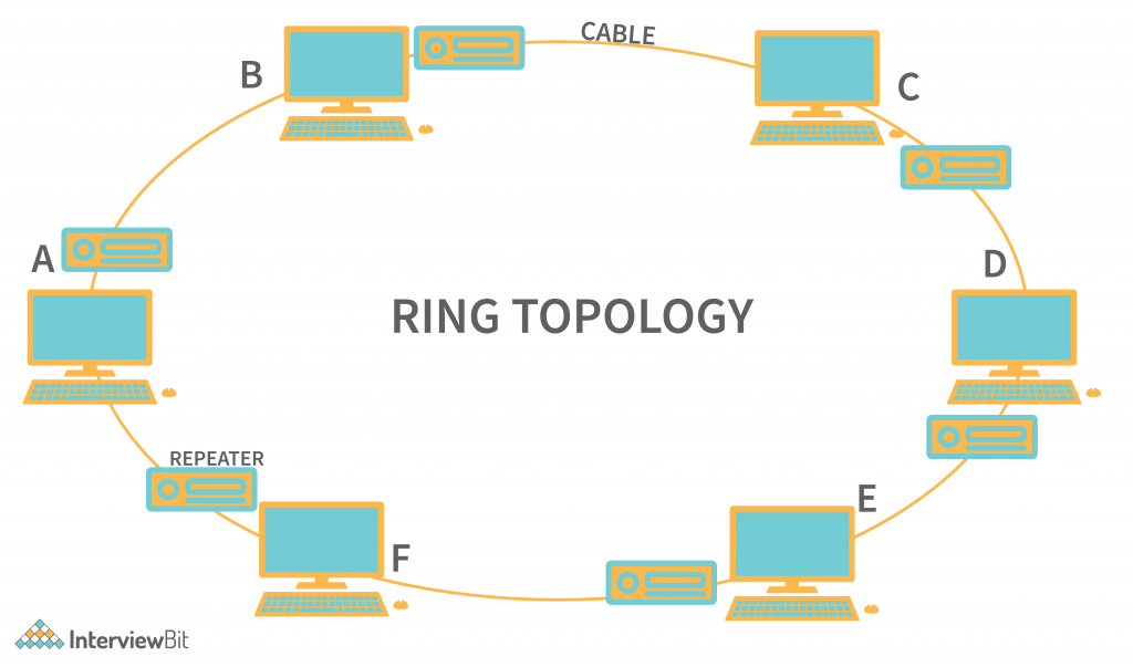
In the above figure, we can see that every node is connected to its neighbour nodes. And the connections between these nodes form a circle shape. So, if Node A wants to send data to Node E then Node A can take two paths to transmit the data. That is –
- Node A → Node F → Node E.
- Node A → Node B → Node C → Node D → Node E.
Once data is received by the node in the network, then with the help of MAC Address (Media Access Control), the Node identifies whether that data belongs to itself or not, and processes the data accordingly.
And one thing to notice is that each node has a Repeater Device connected to it. The repeater is required in case the topology contains large network devices, and transferring the data between the large networks may lead to loss of data. So here the repeater helps to recreate the frame and send it to the following nodes. Ring topology is an active topology because each node plays a role in the transmission of the data.
Protocols Used for Data Transmission in Ring Topology:
Suppose in the case where all the nodes in the ring topology want to transfer the data. And each node transmits the data at the same time. Then the whole data will collide with each other because the data transmitted in the frame is just an electromagnetic signal. This is exactly like we have seen for bus topology. So to avoid this issue, protocols like the Token Ring Passing protocol are used by the workstations for the transmission of data. With this protocol data flows in one direction and only one node is allowed to transmit the data at a time.
Advantages of Ring Topology:
- Easier Troubleshooting – It is easier to manage and install. Because the defects in either nodes or the cable are easily recognizable.
- Less Cabling – Each node manages the cable to its nearest neighbour, so then there is less cabling required.
- Less chance of Data Collision – Token Ring passing topology is mostly used in this topology, which allows only one node to transmit data and is also unidirectional, so there are fewer chances of Data collision.
- Others – They are Well-suited for transmitting signals over long distances on a LAN And they can Handle high-volume network traffic.
Disadvantages of Ring Topology:
- Slow Transmission – As the data needs to be transmitted in each of the nodes to reach the destination. It slows down the network.
- Network Failure – In this, all nodes are connected in a closed loop. So if any fault happens (either on cable or nodes), then the whole network will become paralyzed.
- Difficult in Reconfiguration – If we want to add a node between these networks, then we need to break the cable and the network will shut down. So it can’t be acceptable all the time.
3. Star Topology
In star topology, the nodes are connected to a central hub with point-to-point communication links. Here point-to-point connection means, there is cabling between every node to the central hub. Any data transmitted between these nodes are transferred via the central device.

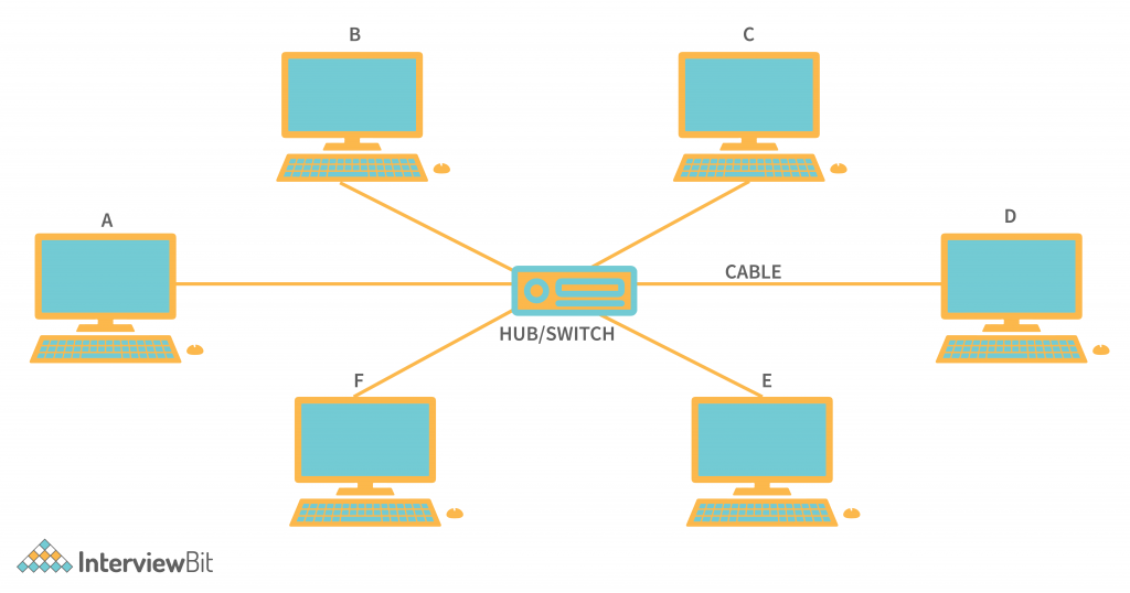
In the above figure, we can see that all the nodes are connected to the central device (HUB/SWITCH). And each node has a connection to the Hub / Switch. This device acts as the link between the nodes. This is one of the most popular topologies used in local area networks. And widely used previously for switching the packets over the central station.
In the above figure of Star Topology, if node A wants to send data to node E. Then the data frame is first transmitted to the central station, and from the central station, the data frame is routed towards the destination node. And this routing is done by the central station (Hub/Switch), based on the MAC (Media Access Control) Address of the nodes. And these MAC addresses are provided by the sender in the data frame itself.
What is used as the central station HUB/SWITCH?
We have seen that HUB or SWITCH can be used as the central station in the star topology. Hub is the multiport repeater and it is used as the broadcaster. This means when the data needs to be sent to all the nodes in the network then HUB is mostly used. On the other hand, when there is unicast data that needs to be transmitted, then switches are used. It already stores the MAC address of each of the nodes connected with it. And routes the frame according to that.
Protocols used in Star Topology:
There are many popular Ethernet LAN protocols there. Like CSMA (Carrier Sense Multiple Access), CD (Collision Detection), etc. These protocols are followed by the whole network for the successful transmission of data between networks. These protocols have a proper frame format in which the data is encapsulated and sent towards the destination.
Advantages of Star Topology:
- Less Expensive – Every node is connected to a central station to transmit the data, so it is less expensive. As it doesn’t require the extra cables to connect one node with all the nodes.
- Easy to Reconfigure – If we needed to add an extra node or remove the node from the network then we need not disconnect the whole network. We simply remove the connection from the central station. And this doesn’t affect the other nodes.
- Easy Fault Detection – It becomes easy to detect faulty nodes by just checking the particular node that is not working.
- Fault Tolerance – One node failure doesn’t affect the whole network, only the node is shut down. So that fault can be tolerated and fixed later on.
Disadvantages of Star Topology:
- Central Failure – This is the biggest disadvantage of star topology. If the HUB/SWITCH itself got disturbed then this breaks the whole network.
- Limited Nodes – The nodes connected to the star topology are limited to the number of physical ports available in HUB/SWITCH.
4. Mesh Topology
In Mesh Topology, every node is connected to as many other nodes as it can be. It is done to avoid the failure of the network in case of any of the one node or cable failure. Mesh Topology is also categorized into two types.
- Partially Connected Mesh Topology.
- Fully Connected Mesh Topology.
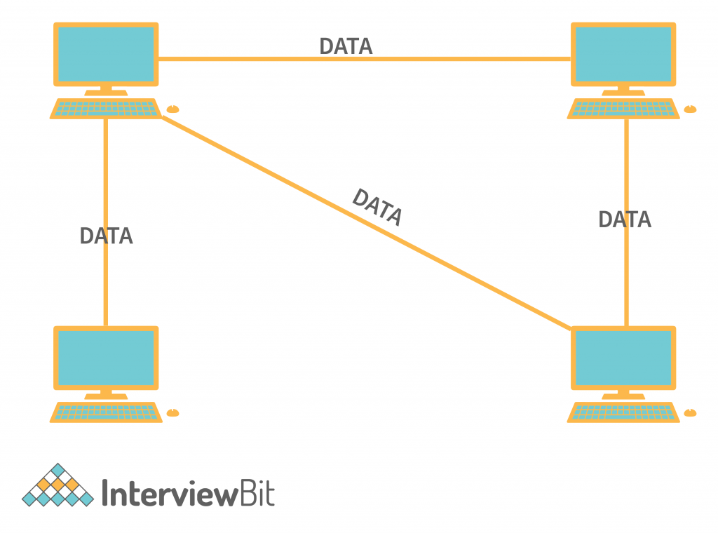
- In Partially Connected Mesh Topology, all nodes are not necessarily directly connected with all the other nodes, but possibly most of the nodes are connected with a point-to-point connection. This helps to avoid shut down of the whole network because of only a single point of failure.

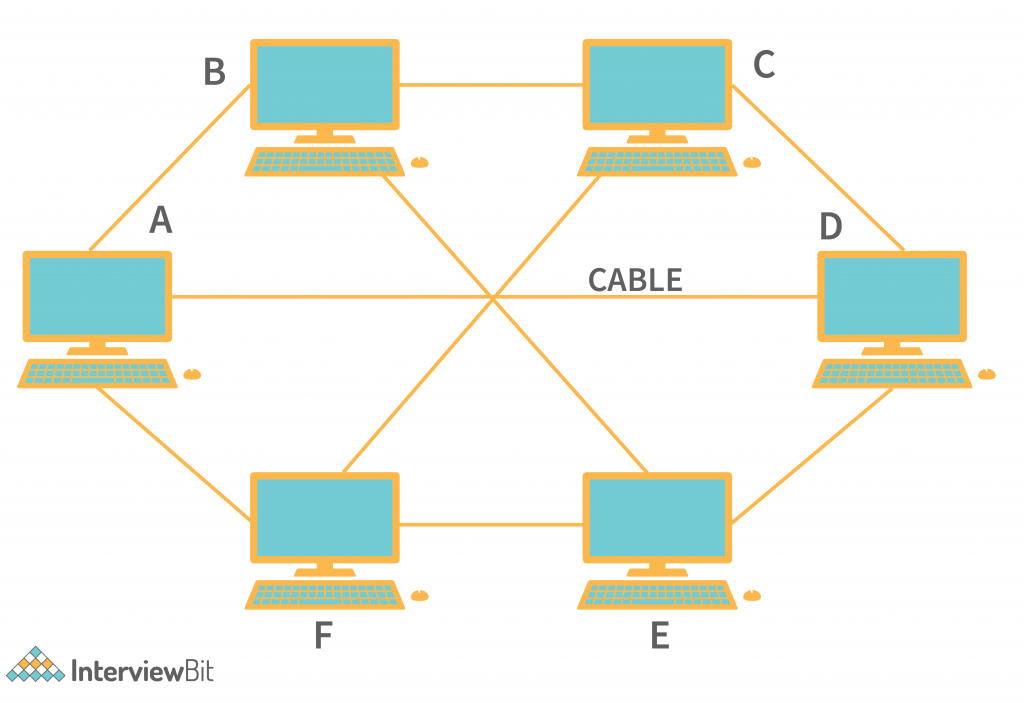
In the above figure, we can see that every node is connected with most of the other nodes in the network, But most of them are covered. Like Node A connected to Node B, Node F and Node D. But not directly connected with Node B and Node E.
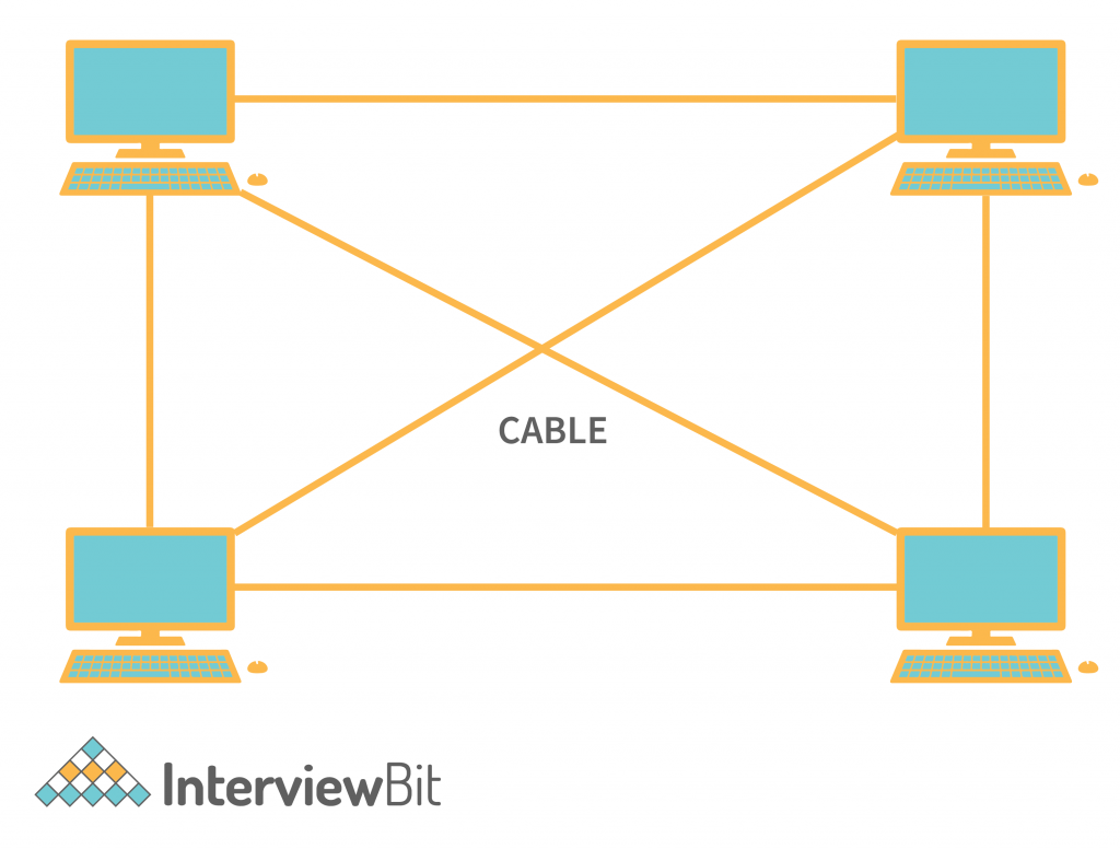
- In Fully Connected Mesh Topology, every node has a direct point-to-point connection with all the other nodes in the network. It reduces the chances of network failure to 0, because of the direct link between all the other nodes.

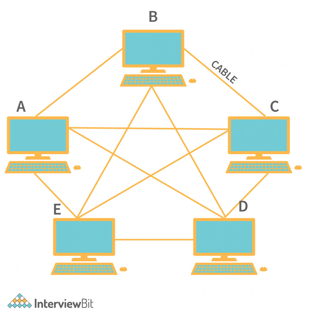
In the above figure, we can see that each node has a direct connection with all the other nodes in the network. And the number of links between these devices can be known with the help of the formula of (Sum of natural numbers between n-1, where n can be any number) → (n*n-1)/2 when there is a duplex channel, which means each data can flow in both directions at the same time. And (n * n-1) for the simplex channel, this means data can flow only in one direction.
For Example- In the above figure, a total of 5 nodes are there. And the total number of links is – (5*4)/2 = 10. And if we consider the same with any number of nodes, then we can easily find the number of links between them.
Protocols used in Mesh Topology:
Generally recognizing each node in the network is a bit difficult if using the MAC address like the ring topology. So the solution to this problem is implementing Standard auto-configuration protocols. The protocols like DHCP (Dynamic Host Configuration Protocol), AHCP (Ad Hoc Configuration Protocols), etc are used.
Advantages of Mesh Topology:
- No Failure – In Mesh topology, there is minimal or no chance of network failure. It is because of the number of links present.
- Privacy and Security – Each node can send data privately to any other node in the network. As each node has separate links (in the case of Fully connected mesh topology), then privacy is maintained.
- No Traffic Problems – As each node will have the maximum number of direct links present, then the traffic flows only for that particular path.
Disadvantages of Mesh Topology:
- Higher Cost – As the number of cables in this topology is higher because each node is directly connected to the maximum number of nodes in the network, then we can say that the cost will also increase.
- Difficult installation – Implementing the mesh topology is a bit difficult because a large number of cabling has to be handled. And that is not a trivial task.
5. Tree Topology
In Tree Topology, all the nodes are connected in a way that they are forming a tree-like structure. These structures of the nodes are used when there are needed to divide the network into the subnetwork. If we just look at the below images then we will find that all the nodes in the network tree are forming the tree structure and Node A is the parent node of all the other nodes in the network.

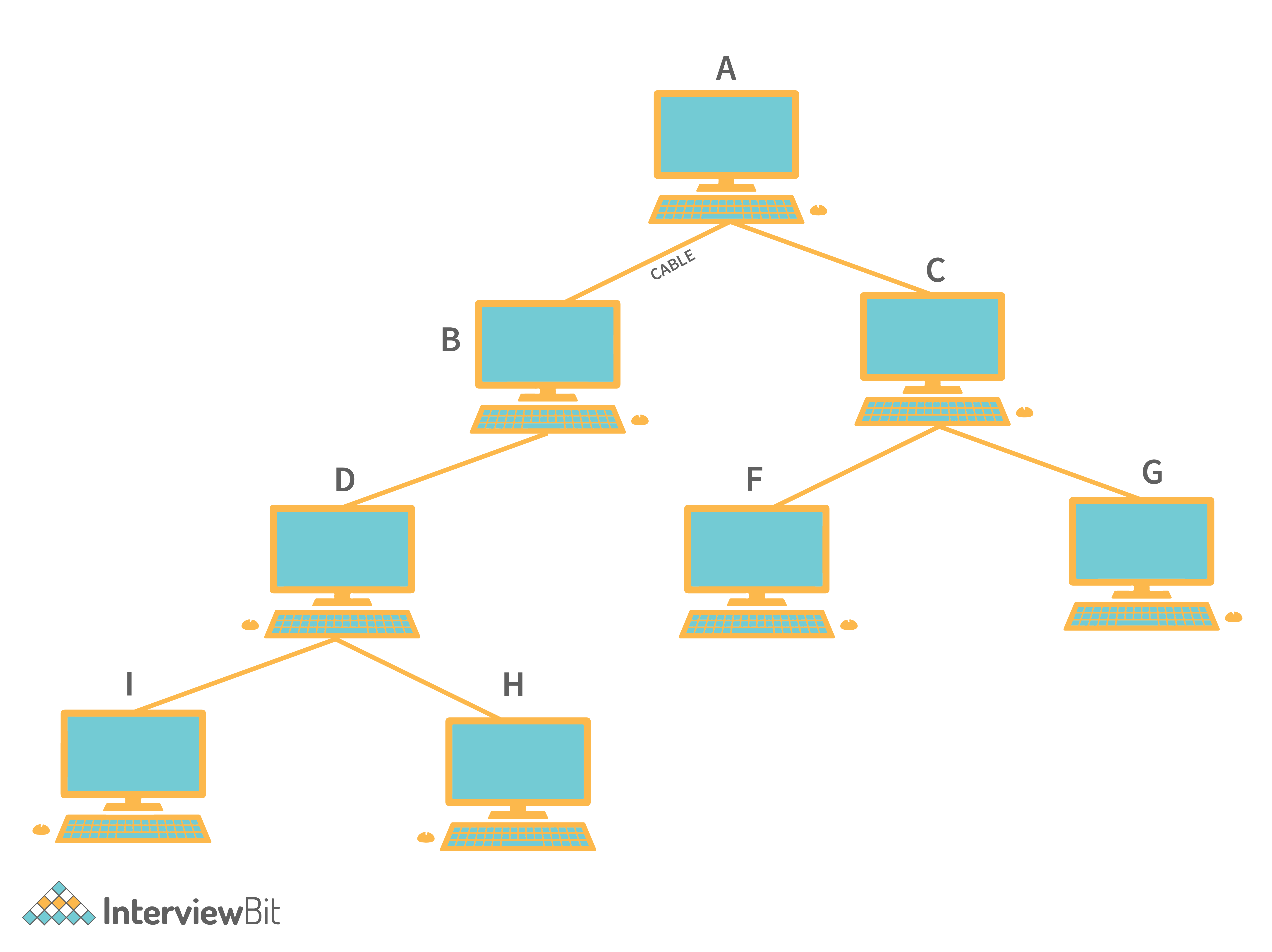
In the above figure, suppose Node I wants to send the data frame to Node G then the frame follows the direction of –
Node I → Node D → Node B → Node A → Node C → Node G.
By following these nodes the data will be successfully received by the destination node. These models are mostly used in server load management.
For Example – If Node A is the main server of any large network. And from the outside network, If any data is requested to Node A then Node A will have to handle all the Requests. So with the help of these, the tasks are distributed to the other Sub Nodes and each sub-nodes separately handles each of these requests.
And in the real-world scenario. These root nodes or any other node in the network need not be the computers. They can also be other networking devices like HUB, Switches, Routers, etc.
Protocols used for Tree Topology:
As we know that in the tree topology, there can be many nodes as a child of the other node. And also there can be other computing devices. And to identify the data coming from which location. We need to keep track of the nodes that are there in the network. And these can also be achieved by the (SAC) Standard Automatic Configuration protocols like DHCP and other SAC.
Advantages of Tree Topology:
- Helps Structuring – The tree-like shape is formed so that any node can hold its child too. And this can help to structure the whole network very quickly.
- All the nodes have access to the large and intermediate networks.
- Expansion of Nodes is possible and can be easily achievable in this network structure.
Disadvantages of Tree Topology:
- Higher Cost – Since managing each node in its child might not be efficient. Cabling costs will also increase. And as well as the quality of the data to most child nodes will not be good.
- Central (Root) Node Failure – If the main central node or other wire becomes faulty then might be all the other nodes will become disconnected.
6. Hybrid Topology
Hybrid technology is the combination of all the different types of topologies we have seen. This structure is used in which the nodes can take any form. This means It can be only Tree Topology, Or it can be only Ring or Star Topology. And as well as it can be a mixture of all the types of network topology we have seen.

In the above figure, This can be configured at multiple sets of network topologies. It can go to multiple levels also.
And it is hard to say that the Hybrid topology follows proper different sets or protocols. Because it contains all the different types of network topology combined, then each separate topology in the hybrid topology uses the protocols that we have already seen.
Conclusion
Network topology describes the set of network networking devices. How they are organized with the cable to form a network. And we have seen different types of network topologies. Like – STAR TOPOLOGY, MESH TOPOLOGY, RING TOPOLOGY, BUS TOPOLOGY, TREE TOPOLOGY, and HYBRID TOPOLOGY.
Now, How do we decide When to use which Network Topology?
Every Network Topology has its own merits and demerits. So while choosing the network topology it can’t be concluded to follow a particular network topology. Instead, there are some points that we need to consider –
- Consider its Cost according to requirement.
- Ease of Installation.
- Ease of Maintenance.
- Fault Tolerance.