Quantum Circuits Explained: Build Your First Quantum Circuit Today


Key Insights
- A quantum circuit represents a sequence of operations that transform qubits and ultimately produce measurable classical results.
- Circuit diagrams use wires for qubits, gate symbols for operations, and measurements to record classical outcomes.
- Reading a quantum circuit from left to right helps track how each operation changes the qubit states.
- The Bell-state circuit demonstrates how an H gate followed by a CNOT can create entanglement and correlated measurement outcomes.
- Circuit width represents the number of qubits, while circuit depth reflects the number of sequential layers of operations, making parallelism important in circuit design.
- Simulators are useful for learning and testing circuits, while real quantum hardware introduces practical factors such as noise, errors, and device-specific constraints.
A quantum circuit is a sequence of operations that acts on qubits to perform a quantum computation. If you are learning quantum computing, the easiest way to understand a quantum circuit is to think of it as a visual timeline: wires represent qubits, boxes and symbols represent quantum gates, and measurement records the final result.
But how do quantum circuits actually work, and how do you read a quantum circuit diagram?
In this guide, we will break down the quantum circuit model, its components, and the basic principles of quantum circuit design. You will also learn how to read circuit diagrams, build a Bell-state circuit step by step, understand circuit depth and width, and compare quantum circuit simulation with execution on real hardware.
What is a Quantum Circuit?
A quantum circuit represents a finite sequence of quantum operations performed on one or more qubits. It provides a structured way to describe how a quantum state changes as it passes through different operations.
The simplest way to picture the flow is:
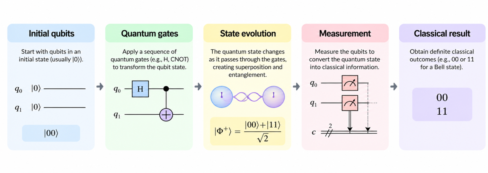
A quantum circuit therefore does more than show which gates are used. It shows the order in which operations act on qubits and how information moves through the computation. IBM describes quantum circuits similarly as networks of gates and measurements connected by wires representing qubits, with circuits generally read from left to right.
From Qubits to Operations
A circuit starts with qubits in an initial state, commonly |0⟩. Quantum gates then transform those states, potentially creating superposition or correlations between qubits.
Finally, measurement extracts a classical outcome from the quantum state. This makes the quantum circuit model a useful bridge between an abstract quantum algorithm and the sequence of operations needed to implement it.
What are the Components of a Quantum Circuit?
Understanding the basic quantum circuit components makes larger diagrams much easier to read.
Qubits and Quantum Wires
Each horizontal wire represents a qubit. The wire tracks that qubit as it moves through the circuit from left to right.
A circuit may contain a single qubit or many qubits. For example:
q₀: ─────────
q₁: ─────────
q₂: ─────────
This represents a three-qubit circuit.
Quantum Gates
Quantum gates are operations that transform the state of one or more qubits. Some of the most useful quantum circuit gates for beginners are:
- X: flips |0⟩ to |1⟩ and |1⟩ to |0⟩.
- H: creates or changes superposition.
- Z: applies a phase flip.
- CNOT: performs a controlled operation involving two qubits.
You do not need to memorise every available gate to understand quantum circuit design basics. Start by learning what each symbol does and which qubits it acts on.
Measurement and Classical Bits
Measurement converts quantum information into a classical outcome. In a circuit diagram, a measurement can connect a qubit to a classical bit:
q₀: ─────M──
│
c₀: ══════╩═
The measured result is recorded in the classical register. In Qiskit-style diagrams, quantum wires and classical wires are therefore visually distinct.
How to Read a Quantum Circuit Diagram?
A quantum circuit diagram becomes much easier to understand if you follow the same process every time.
Start With the Qubit Wires
First, count the wires and identify which qubit each one represents. Then check the initial state.
Ask:
- How many qubits are present?
- What is their initial state?
- Which wire corresponds to which qubit?
Follow Gates From Left to Right
Quantum circuits are normally read from left to right. For every operation, ask four questions:
- Which qubit does the gate act on?
- Is it a single- or multi-qubit operation?
- What does the operation do to the state?
- What happens next?
This approach lets you understand how quantum circuits work without immediately relying on mathematical notation.
Recognise Multi-Qubit Connections
A connection between two wires usually indicates an operation involving both qubits. A common example is the CNOT gate:
q₀: ──●──
│
q₁: ──X──
Here, the ● represents the control qubit and the X/⊕ symbol represents the target. The target operation depends on the state of the control qubit.
A CNOT can be used to create entanglement, but it does not automatically entangle every input state. Its effect depends on the state entering the gate.
Identify the Measurement Stage
Measurement is usually placed toward the end of a circuit. It converts the quantum state into classical information that can be recorded and interpreted.
How to Build a Bell-State Circuit Step by Step?
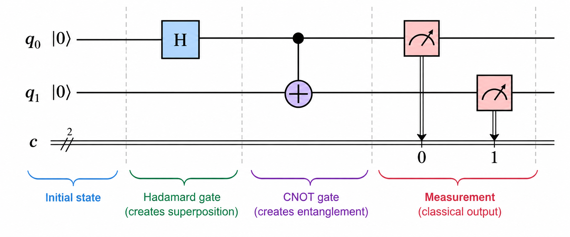
A Bell-state circuit is one of the best quantum circuit examples for beginners because it shows how superposition and a two-qubit operation work together.
The basic circuit is:
q₀: ──H──●──M──
│
q₁: ─────X──M──
This circuit applies an H gate to the first qubit, followed by a CNOT, and then measures both qubits. This is the standard construction for the |Φ⁺⟩ Bell state.
Step 1 — Start With Two Qubits
The circuit begins with two qubits in the state: |00⟩
Neither qubit has been transformed yet.
Step 2 — Apply H to the First Qubit
The Hadamard gate puts the first qubit into an equal superposition: |00⟩ → (|00⟩ + |10⟩)/√2
The first qubit can now be understood as having both computational-basis possibilities represented in the state, while the second qubit remains unchanged.
Step 3 — Apply CNOT
Next, the CNOT uses the first qubit as its control and the second as its target: (|00⟩ + |10⟩)/√2 → (|00⟩ + |11⟩)/√2
The resulting state is: |Φ⁺⟩ = (|00⟩ + |11⟩)/√2
This is a Bell state, demonstrating quantum circuit entanglement.
Step 4 — Measure Both Qubits
When both qubits are measured, the ideal outcomes are:
00
11
with approximately equal probabilities.
The important idea is the correlation between the results: if the first qubit is measured as 0, the second is also 0; if the first is 1, the second is also 1.
What are Quantum Circuit Width and Depth?
Two useful ways to describe a circuit are its width and depth.
Circuit Width
For a beginner-level quantum circuit, width primarily refers to the number of qubits represented:
q₀: ─────────
q₁: ─────────
q₂: ─────────
This is a three-qubit circuit, so its width is three qubits.
Circuit Depth
Quantum circuit depth refers to the number of sequential layers needed to execute the circuit, taking parallel operations into account.
For example:
q₀: ──H──X────
q₁: ──H──X────
The two H gates can operate in parallel, so they occupy the same layer. The X gates form the next layer. Therefore, circuit depth is not simply the total number of gates. IBM similarly defines depth in terms of layers of gates that can be executed in parallel.
Why Lower Depth Can Matter?
On real quantum hardware, deeper circuits can mean longer execution and greater exposure to noise and errors. This makes reducing unnecessary depth an important part of quantum circuit design.
However, shallower is not automatically better. The circuit still needs enough operations to perform the required computation.
Quantum Circuit Simulator vs Real Quantum Hardware
A quantum circuit simulator allows you to study the behaviour of a circuit without immediately running it on a physical quantum processor.
What Does a Quantum Circuit Simulator Do?
Quantum circuit simulation uses classical computing resources to model how a quantum circuit behaves. For beginners, simulation is useful for:
- Learning circuit behaviour
- Testing and debugging
- Checking expected results
- Experimenting with different circuits
- Comparing outputs before hardware execution
This makes quantum circuit simulation a practical starting point for circuit design.
What Changes on Real Quantum Hardware?
A real quantum circuit runs on physical qubits, so its results are affected by factors such as:
- Noise
- Gate errors
- Measurement errors
- Hardware connectivity
- Device-specific constraints
An abstract circuit may also need to be compiled or transpiled so that its instructions match the capabilities and connectivity of a particular quantum processor.
When Should a Beginner Use Each?
| Simulator | Real hardware |
|---|---|
| Learn circuit behaviour | Test physical execution |
| Debug circuits | Observe hardware noise |
| Check expected outputs | Study hardware constraints |
| Experiment quickly | Evaluate real-device performance |
Common Quantum Circuit Patterns
Recognising common quantum circuit patterns makes unfamiliar diagrams easier to interpret. These patterns form a useful foundation for recognising more advanced quantum circuits later.
Superposition Pattern
q₀: ──H──
An H gate can move a computational-basis qubit into an equal superposition.
Bit-Flip Pattern
q₀: ──X──
The X gate exchanges |0⟩ and |1⟩.
Entanglement Pattern
q₀: ──H──●──
│
q₁: ─────X──
Starting with |00⟩, the H + CNOT pattern prepares a Bell state.
Measure-and-Readout Pattern
q₀: ──H──M──
The measurement converts the quantum state into a classical outcome that can be recorded and analysed.
Conclusion
Quantum circuits provide the practical framework for turning quantum operations into a sequence that can be designed, read, tested, and executed. By understanding qubits, gates, measurement, circuit depth and width, and patterns such as the Bell-state circuit, you have the foundation needed to reason about more advanced quantum algorithms and applications.
Ready to take your quantum computing skills beyond circuit fundamentals? Explore Applied Quantum Computing & AI programme by IIT Delhi, delivered on Varsity by InterviewBit, takes you from quantum foundations and circuit design to Qiskit programming, real quantum hardware, and hands-on projects with industry-focused capstones.
Frequently Asked Questions
How does a quantum circuit create entanglement?
Entanglement can be created by applying suitable multi-qubit gates to an appropriate input state. A common example is the Bell-state circuit, where an H gate creates superposition and a following CNOT links the two qubits, producing correlated measurement outcomes.
What is a quantum circuit simulator?
A quantum circuit simulator uses classical computing to model how a quantum circuit behaves. It is useful for learning, testing, debugging, and checking expected results before running the same circuit on physical quantum hardware.
What is the difference between a quantum simulator and real quantum hardware?
A simulator models circuit behaviour using classical computation, often under idealised assumptions. Real quantum hardware uses physical qubits and therefore introduces noise, gate errors, measurement errors, connectivity constraints, and other device-specific effects.
What is the difference between a quantum circuit and a quantum algorithm?
A quantum algorithm is the broader computational procedure for solving a problem using quantum principles. A quantum circuit is a concrete representation of the operations needed to implement that procedure on qubits.
Can quantum circuits be run without real quantum hardware?
Yes. Many small quantum circuits can be simulated classically, allowing beginners to explore circuit behaviour without access to a quantum processor. However, classical simulation becomes increasingly demanding as circuit size grows and does not reproduce every practical constraint of real hardware.
Can two quantum gates act at the same time?
Yes. Gates acting on different qubits can often be performed in parallel and placed in the same circuit layer. This is why circuit depth is different from simply counting the total number of gates.
Can a quantum circuit have more gates but a smaller depth?
Yes. Several gates may operate simultaneously on different qubits, allowing a circuit with more total gates to have fewer sequential layers than another circuit. Gate count and circuit depth therefore measure different aspects of a circuit.
Does every quantum circuit need a CNOT gate?
No. CNOT is especially useful for multi-qubit operations and entanglement, but a quantum circuit can contain only single-qubit gates or even consist of a single operation. Its inclusion depends on what the circuit needs to accomplish.
Why do some quantum circuit diagrams have two types of wires?
Quantum wires carry qubits through the circuit, while classical wires carry information produced by measurements. In many circuit diagrams, quantum wires are shown as single lines and classical registers as double or otherwise visually distinct lines.
What is a quantum circuit for beginners?
A beginner-friendly quantum circuit is one that uses a small number of qubits and familiar operations such as H, X, CNOT, and measurement. A Bell-state circuit is a useful first example because it demonstrates superposition, multi-qubit operations, and measurement in one compact circuit.