Introduction
ER Model stands for Entity-Relationship Model, also known as a high-level data model that shows the relationship among the entity sets.ER Model is used to define the entities and the relationships between them.
It helps developers to design the conceptual design or you can say the logical design of the system from a data perspective.ER model describes the structure of a database with the help of a diagram, which is known as the Entity-Relationship Diagram (ER Diagram).
What is an ER Diagram?
ER diagrams are used to sketch out the design of a database. By defining the entities, their attributes, and showing the relationships between them, an ER diagram illustrates the logical structure of databases.ER diagrams are created based on three basic concepts: entities, attributes, and relationships.

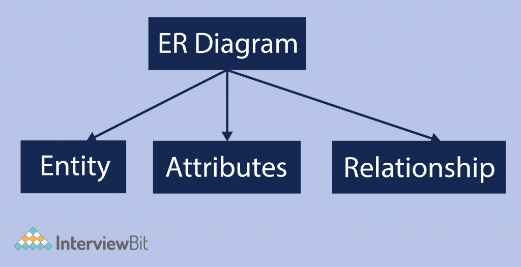
As shown in the above diagram, an ER diagram has three main components:
- Entity
- Attribute
- Relationship
Entity
Any object that physically exists and is logically constructed in the real world is called as an entity. It is a real-world object that can be easily identifiable. An entity is represented as a rectangle in an ER diagram.
Example- In an organization, employees, managers, and projects assigned can be considered entities. All these entities have some attributes or properties that give them their identity.


Here, in the above example, employee and project are entities.
Entities are of two types:
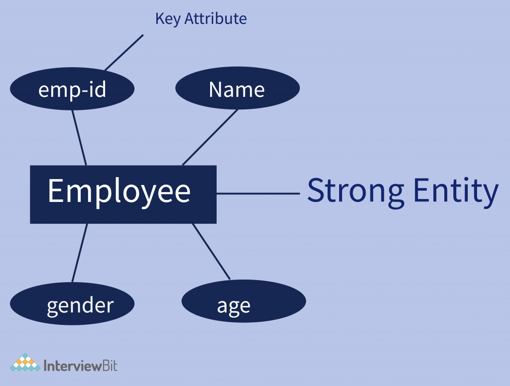
- Strong Entity – Strong entities are those entity types that have a key attribute. The primary key helps in identifying each entity uniquely. this can not accept null values so it can not be a unique key. It is represented by a rectangle.
Example – in an example of organization emp_id identifies each employee of the organization uniquely and hence, we can say that employee is a strong entity type.

- Weak Entity – Weak entity type doesn’t have a key attribute. Weak entity types can’t be identified on their own. It depends upon some other strong entity for its distinct identity. A weak entity is represented by a double outlined rectangle. The relationship between a weak entity type and strong entity type is shown with a double outlined diamond instead of a single outlined diamond. This representation can be seen in the example given below.
Here we cannot identify the address uniquely as there can be many employees from the same locality. So, for this, we need an attribute of Strong Entity Type i.e ‘employee’ here to uniquely identify entities of ‘Address’ Entity Type.
Attribute
An attribute is a property or characteristic of an entity. An entity may contain any number of attributes. The attributes that can uniquely define an entity are considered as the primary key. In an Entity-Relation model, attributes are represented in an elliptical shape. It also may refer to a database field. Attributes describe the instances in the database.
A database consists of tables. Each table has columns and rows. The columns in a database are called attributes.
Example: Employee has attributes like name, age, roll,emp_id, and many more. To uniquely identify the employee, we use the primary key as an emp_id(employee id) as it is not repeated. Attributes can also be subdivided into another set of attributes.
There are five such types of attributes:
- Simple attribute
- Composite attribute
- Single-valued attribute
- Multi-valued attribute
- Derived attribute.
Note:- There is also one more attribute i.e; complex attribute. This is the rarely used attribute.
- Simple attribute–Attributes that are not further divisible into sub-attributes (atomic) are known as Simple attributes.
Example: The roll number of a student, the id number of an employee.
It is also called a key attribute. It modeled in ER diagram as a simple eclipse with underlined attribute name.
- Composite attribute– Composite attributes can be divided into sub-attributes which represent more basic attributes with independent meanings.
Example: the Address attribute of the EMPLOYEE entity shown can be subdivided into Street_address, City, State, and Pincode.
Composite attributes are useful to model situations in which a user sometimes refers to the composite attribute as a unit but at other times refers to its components.
If the composite attribute is referenced only as a whole, there is no need to subdivide it into component attributes. For example, if there is no need to refer to the individual components of an address (Zip Code, street, and so on), then the whole address can be designated as a simple attribute.
- Single-valued attribute– Attributes having single value for a particular entity instance is known as single-valued attribute.
Example, the age of a person is single-valued.
- Multi-valued attribute–There are many instances where an attribute has a set of values for a specific entity, known as Multivalued attributes.
Multivalued attributes are modeled in ER using a double circle.
Example: Phone number. A person may have zero, one or more phone numbers, and different employees may have different numbers of phones.
- Derived attribute–The value for this type of attribute can be derived from the values of other related attributes or entities instances.
Example: suppose that the employee entity set has an attribute age, which indicates the employee’s age. If the employee entity set also has an attribute date-of-birth, we can calculate age from date-of-birth and the current date. Thus, age is a derived attribute.
However, the derived attribute needs to be computed every time it’s required.
- Complex attribute–Complex attributes are formed by nesting composite and multivalued attributes arbitrarily.These attributes are rarely used in DBMS(DataBase Management System). That’s why they are not so popular.
These (multi-valued and composite attributes are called ‘Components’ of complex attributes) components are grouped between parentheses ‘( )’ and multi-valued attributes between curly braces ‘{ }’, Components are separated by commas ‘, ‘.
Example: let us consider an employee having multiple phone numbers, emails, and an address.
Here, phone number and email are examples of multi-valued attributes and address is an example of the composite attribute, because it can be divided into house number, street, city, and state.
empAdd_empPhone({email},{Phone},Address{Housenumber,city,state})
Here ,empAdd_empPhone is a complex attribute.
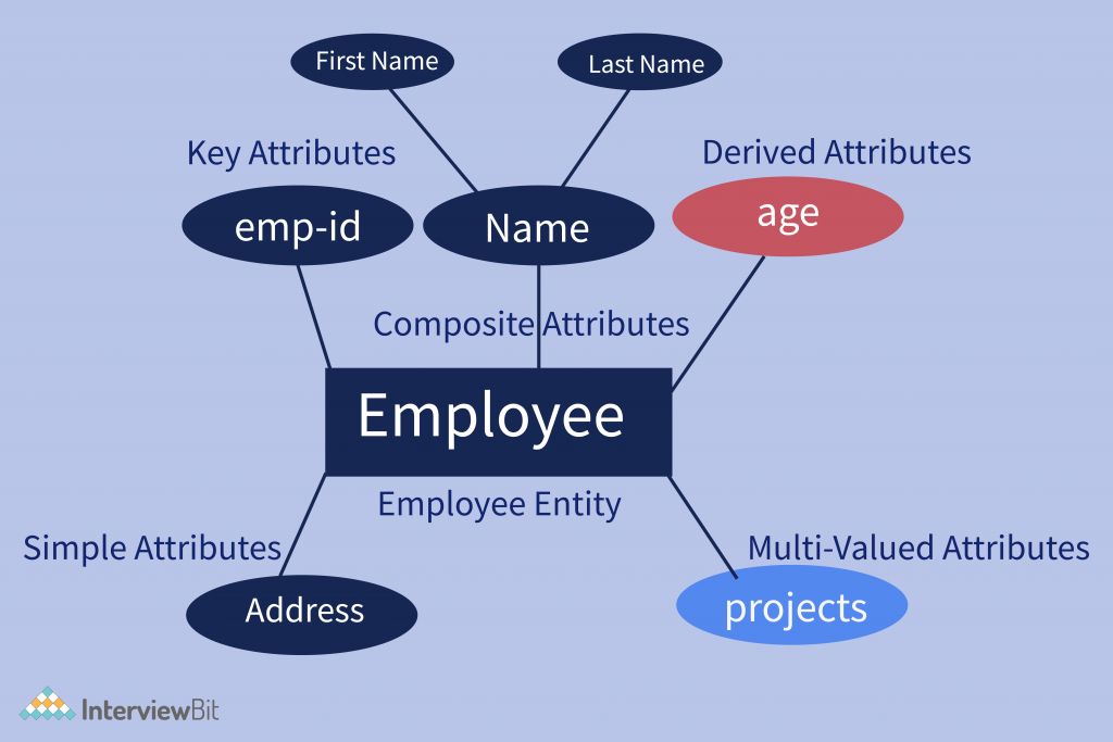
Here is the figure is given below represents all the attributes in the ER diagram:

Relationship
A relationship in a DBMS is primarily the way two or more data sets are linked. Relationships allow the datasets to share and store data in separate tables. They also help link disparate data with each other.
A relationship, in the context of databases, is a situation that exists between two relational database tables when one table has a foreign key that references the primary key of the other table. Relationships allow relational databases to split and store data in different tables while linking disparate data items.
Relationships are of three types and the next segment talks about the same.
Types of relationships
- One to One
- One to Many
- Many to Many
Let us see what each one of them entails.
One to One – It is used to create a relationship between two tables in which a single row of the first table can only be related to one and only one record of a second table. This relationship tells us that a single record in Table A is related to a single record in Table B. And vice versa.
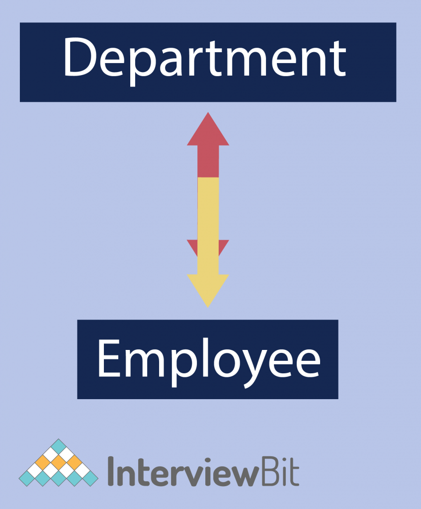
Example – In a university, each department has only one head of the department. And one HOD can take only one department. This shows a one-to-one (1:1) relationship between the department and the person as a head.


One to Many – It is used to create a relationship between two tables. Any single row of the first table can be related to one or more rows of the second table, but the rows of the second table can only relate to the only row in the first table. It is also known as a many-to-one relationship.
Example: of a 1:M relationship is A department that has many employees, Each employee is assigned to one department.

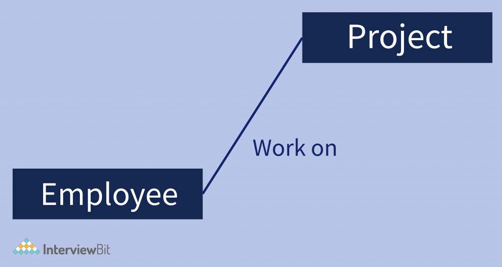
Many to Many – Many to many relationships that create a relationship between two tables. Each record of the first table can relate to any records (or no records) in the second table. Similarly, each record of the second table can also relate to more than one record of the first table. It also represented an N:N relationship.
Example: there are many employees involved in each project, and every employee can involve in more than one project.

Features of ER model
The basic E-R concepts can model most database features, some aspects of a database may be more aptly expressed by certain extensions to the basic E-R model. The extended E-R features are specialization, generalization, higher- and lower-level entity sets, attribute inheritance, and aggregation.
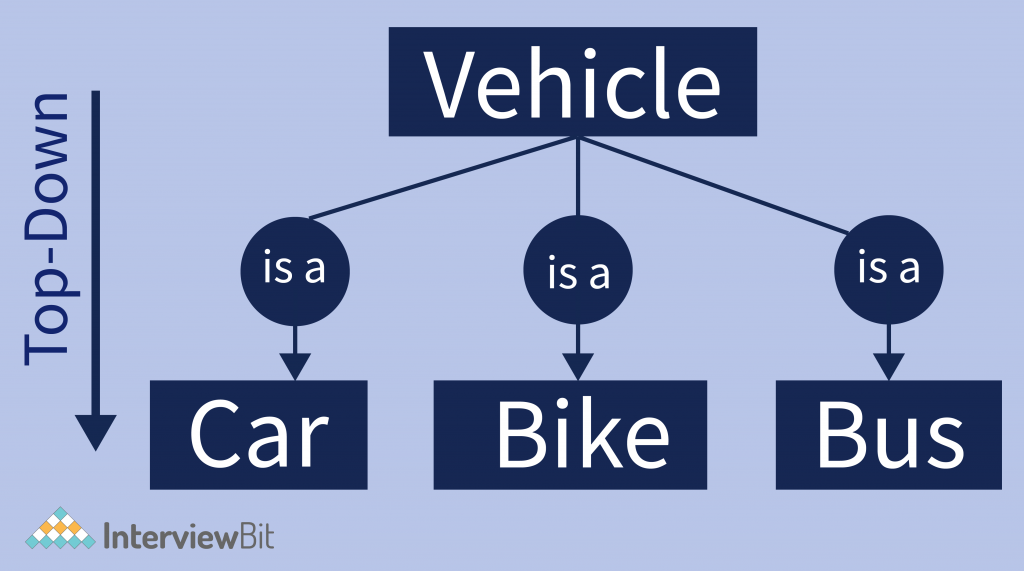
Specialization – An entity set broken down sub-entities that are distinct in some way from other entities in the set. For instance, a subset of entities within an entity set may have attributes that are not shared by all the entities in the entity set. The E-R model provides a means for representing these distinctive entity groupings.
Specialization is an “aTop-down approach” where a high-level entity is specialized into two or more level entities.
Example – Consider an entity set vehicle, with attributes color and no. of tires. A vehicle may be further classified as one of the following:
- Car
- Bike
- Bus
Each of these vehicle types is described by a set of attributes that includes all the attributes of the entity set vehicle plus possibly additional attributes. For example, car entities may be described further by the attribute gear, whereas bike entities may be described further by the attributes automatic break. The process of designating subgroupings within an entity set is called specialization. The specialization of vehicles allows us to distinguish among vehicles according to whether they are cars, buses, or bikes.

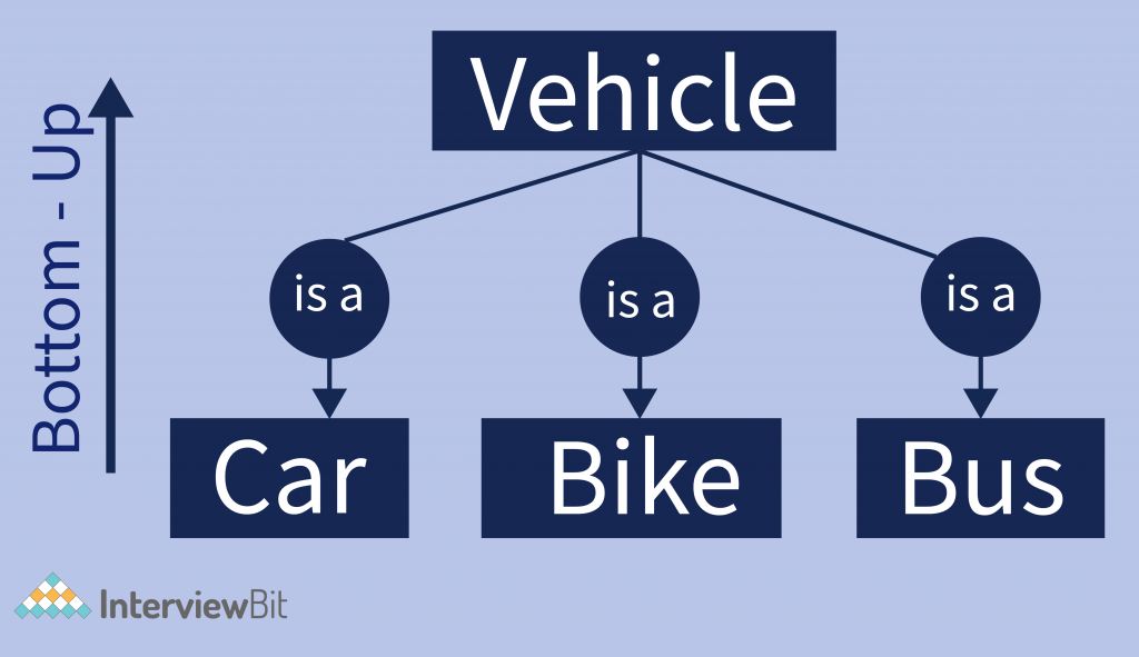
Generalization – It is a process of extracting common properties from a set of entities and creating a generalized entity from it. Generalization is a “Bottom-up approach”. In which two or more entities can be combined to form a higher-level entity if they have some attributes in common.
In generalization, Subclasses are combined to make a superclass.
Example: There are three entities given, car, bus, and bike. They all have some common attributes like all cars, buses, and bikes they all have no. of tires and have some colors. So they all can be grouped and make a superclass named a vehicle.

Inheritance – An entity that is a member of a subclass inherits all the attributes of the entity as the member of the superclass, the entity also inherits all the relationships that the superclass participates in. Inheritance is an important feature of Generalization and Specialization. It allows lower-level entities to inherit the attributes of higher-level entities.
Example – Car, bikes, and buses inherit the attributes of a vehicle. Thus, a car is described by its color and no. of tires, and additionally a gear attribute; a bike is described by its color and no. of tires attributes, and additionally automatic break attribute.
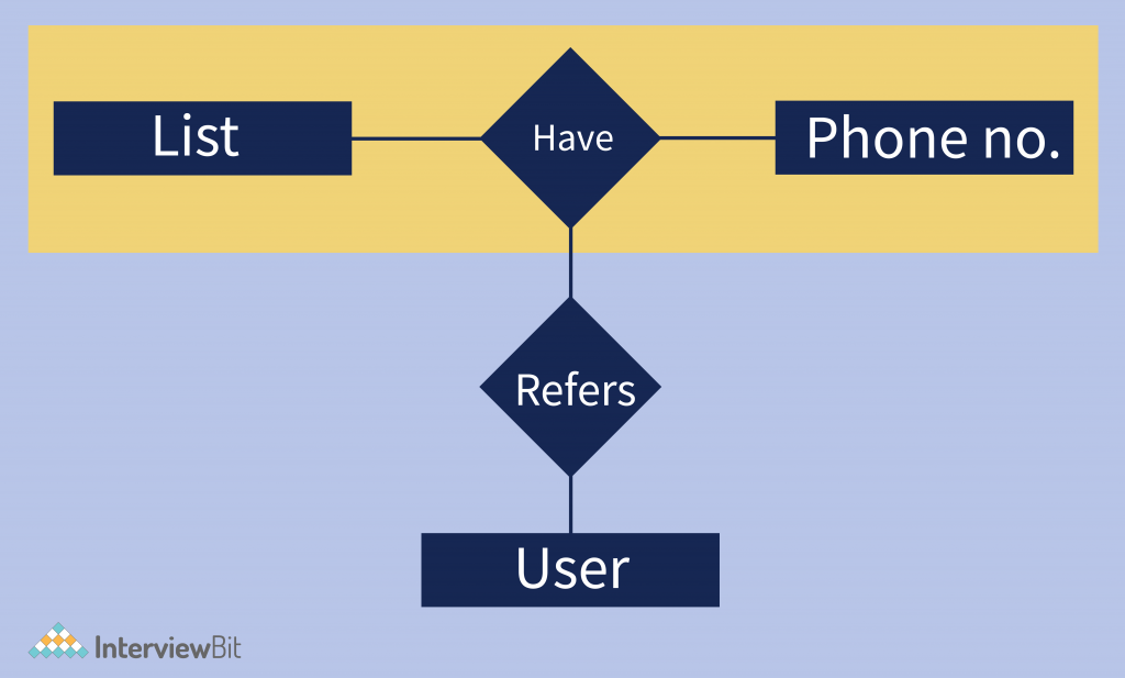
Aggregation – In aggregation, the relation between two entities is treated as a single entity. In aggregation, the relationship with its corresponding entities is aggregated into a higher-level entity.
Example- phone numbers on your mobile phone. You can refer to them individually – your mother’s number, your best friend’s number, etc. But it’s easier to think of them collectively, as your phone number list. It is also important to realize that each member of the aggregation still has the properties of the whole. In other words, each phone number in the list remains a phone number. The process of combining them has not altered them in any way.

How To Create ER diagram in DBMS
Following are the steps to create an ER Diagram

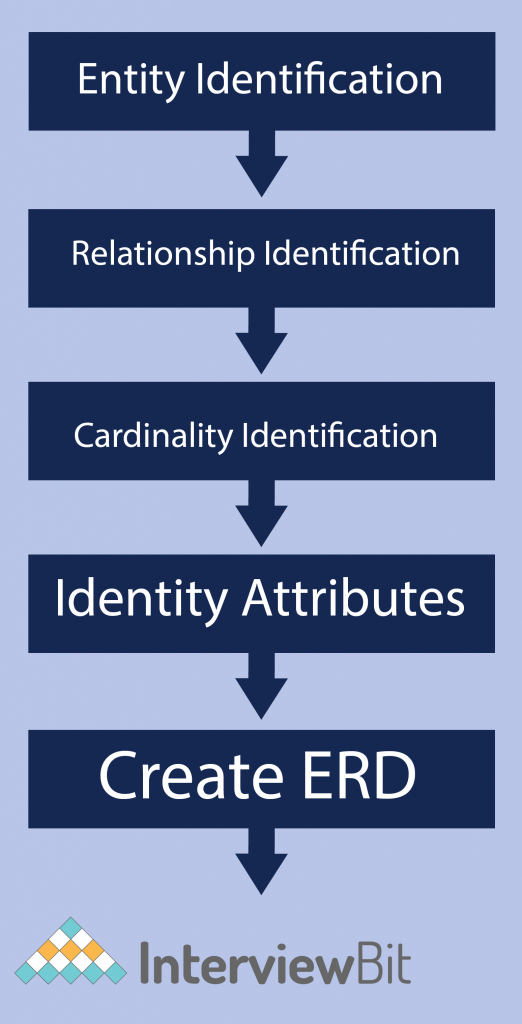
Let’s study them with an Entity Relationship Diagram Example:
In an Organization, an employee is assigned to projects. An employee must be assigned to at least one or more projects. Each project is managed by a single manager. To maintain instruction quality, a manager can control only one project.
Step 1) Entity Identification: We have three entities
- Employee
- Project
- Manager


Step 2) Relationship Identification: We have the following two relationships
- The employee is assigned a project
- manager control a project


Step 3) Cardinality Identification: For them problem statement we know that,
- An employee can be assigned multiple projects
- A manager can manage only one course


Step 4) Identify Attributes – Initially, it’s important to identify the attributes without mapping them to a particular entity. Once you have a list of Attributes, you need to map them to the identified entities. Ensure an attribute is to be paired with exactly one entity. If you think an attribute should belong to more than one entity, use a modifier to make it unique.
Once the mapping is done, identify the primary Keys. If a unique key is not readily available, create one.
| Entity | Primary Key | Attribute |
|---|---|---|
| Employee | Employee_ID | EmployeeName |
| Manager | Manager_ID | ManagerName |
| Project | Project_ID | ProjectName |
For the sake of ease, we have considered just one attribute.
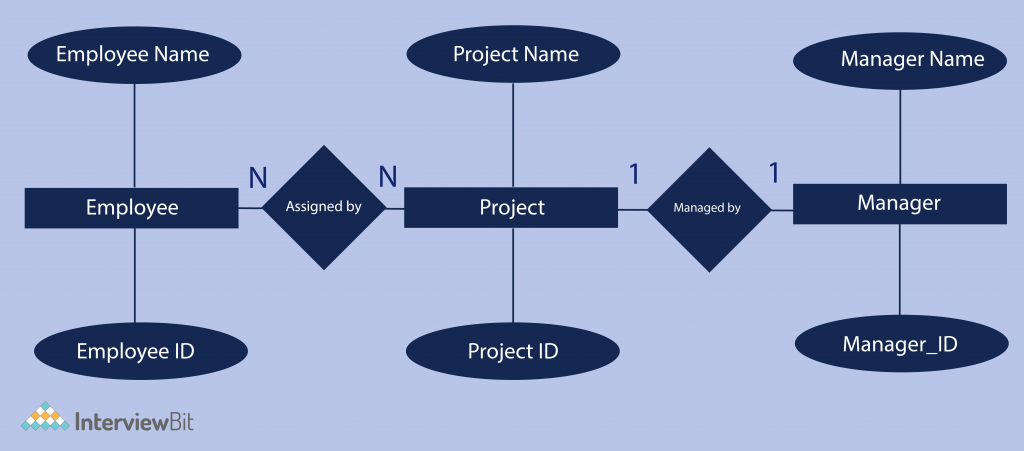
Step 5) Create the ERD Diagram – A more modern representation of Entity Relationship Diagram Example

Why use ER Diagrams?
Here, are prime reasons for using the ER Diagram
- It helps you to define terms related to entity relationship modeling.
- It provides a preview of how all your tables should connect, what fields are going to be on each table
- It helps to describe entities, attributes, relationships.
- ER diagrams are translatable into relational tables which allows you to build databases quickly.
- ER diagrams can be used by database designers as a blueprint for implementing data in specific software applications.
Conclusion
ER diagram in DBMS is widely used to describe the conceptual design of databases. It helps both users and database developers to preview the structure of the database. With the help of an ER diagram, we can create the required database and perform queries. For Example in the case of the airline reservation system, we can make queries like to find the scheduled time of a flight, the number of booked seats in a flight, flight fares, etc. We can convert the ER design into a relational design or you can say table format.