
Introduction
TCP (Transmission Control Protocol), IP (Internet Protocol) is the collection of protocols that allows the computers to connect with the network and exchange data with other computers over the Network.The TCP/IP model is the foundation of the Internet that was introduced by the U.S. Department of Defence (DoD). At that time Internet was not so popular. After this, Internet slowly became popular.
TCP/IP protocols are based and implemented on the reference of the OSI Model (Open System Interconnection). OSI Model is the theoretical model that defines some set of protocols that need to be followed by every network for the successful transmission of data over the network. Most networking systems that we encounter today follow the TCP/IP model. TCP/IP Model much simplified practical model that is practically used in the real world.
Why TCP/IP
TCP/IP Model is a more optimized and practically implemented model. It has taken the reference from the OSI Model and put a lot of emphasis on accuracy. It includes several steps that ensure the data sent from one host to another host must reach on without any failures, or in the case, failure or loss of data happens then It doesn’t need to retransmit the whole data. Instead, it only sends the incorrect data or the data.
And to achieve this, there are a lot of excellently designed algorithms that run behind to make this possible.
Confused about your next job?

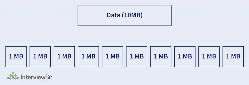
Explanation – Suppose, there are two hosts (computers) Host A and B. And Host A wants to send 10MB of data to Host B. For this, According to TCP/IP Model Protocols, the data is divided into small pieces and then it will be sent.
Note: Here in this example 1MB each, But it is not necessarily that it will be of fixed size and 1MB. Packets sizes are mostly in KB (KiloByte).
Layers in TCP/IP Model –
TCP/IP Model is a practically implemented version of the OSI Model. Although layers are different in TCP/IP Model in comparison with the OSI Model. The layers are grouped according to the task performed by each layer. It has commonly 4 layers. But somewhere it has been considered as 5 Layers. So the common 4 layers of the TCP/IP Model is –
- Application Layer
- Transport Layer
- Network Layer
- Network Interface Layer
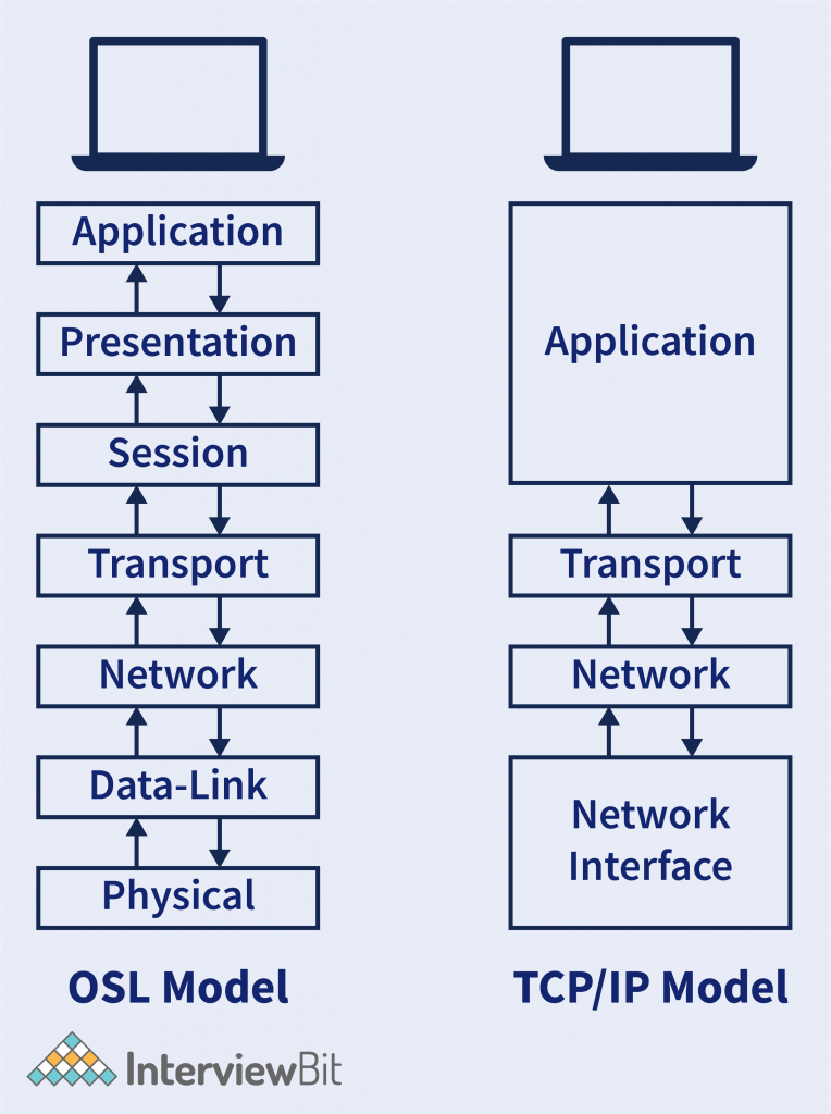
- In the OSI Model, we have the first four layers that have the responsibility of the Host. And the rest 3 layers have the responsibility of the Network.
Similarly in TCP/IP Model we have the first half is the responsibility of the Host and another half is the responsibility of the Network. - There is the logical combination of the first 3 layers of the OSI Model (Application, Presentation, and Session Layer) into the single layer in the TCP/IP Model called the Application Layer. It has combined because all the first three layers of the OSI Model have been performed by each application itself.
Example – Browser does all the 3 work done by the Application, Presentation, and Session Layer. So why there can be a separate layer for each? So TCP/IP Model defines that the task related to individual applications are being performed in the application layer. - In the OSI Model, we have the first four layers that have the responsibility of the Host. And the rest 3 layers have the responsibility of the Network.
- Similarly in TCP/IP Model we have the first half is the responsibility of the Host and another half is the responsibility of the Network.
- There is the logical combination of the first 3 layers of the OSI Model (Application, Presentation, and Session Layer) into the single layer in the TCP/IP Model called the Application Layer. It has combined because all the first three layers of the OSI Model have been performed by each application itself.
- Example – Browser does all the 3 work done by the Application, Presentation, and Session Layer. So why there can be a separate layer for each? So TCP/IP Model defines that the task related to individual applications are being performed in the application layer.
- Similarly, the last 2 Layer of the OSI model (Data-Link layer and the Physical Layer) is also logically combined into the single layer called Network-Interface Layer. This combined is also because these two layers deal with the mediums (wireless or wired). So logically this is combined into a single layer.
TCP/IP Model with 5 Layers
The last two layers of the OSI Model (Data-Link and Physical Layer) deals with the network medium. Which Data-Link Layer task is to convert the packets into Bits of Frames and other Physical layer Deals with BitStream Signals to the medium. So in TCP/IP Model with 5 layers have separated these 2. So TCP/IP Model with 5 layers are –
- Application Layer
- Transport layer
- Network Layer
- Data-link Layer
- Physical Layer
Note:- In this article, we will understand the TCP/IP Model in terms of the 5 Layered Model.
Application Layer
This layer deals with the application part. Applications that require communication with the network, then the protocols defined in the application layer will be followed by the applications for transmission of data. There are a bunch of protocols that are followed by individual applications that need to transmit the data to the network or fetch data from the network.
At the front of the Applications, the data originated will be processed by the application layer. So some of the applications that interact with the internet follow protocols, like –
- Browser —- HTTP / HTTPS, FTP, DNS
- Outlook —- SMTP
- WhatsApp —- Customized (XMPP).
- Remote Desktop —- Telnet, RDP.
- HTTP/HTTPS – (Hypertext Transfer Protocol).
- This is the most popular protocol used by webpage and whole (www) itself. Every time we browse for the webpage, this is the protocol that is used in the background to bring the web page from the server to our client machine. HTTP uses Port Number 80 to communicate between all clients and servers and HTTPS uses TCP port 443. There can be many applications that are using the network to send packets. So Port Number is the 16-bit number that is used by the application for the identification of packets that belongs to which application.
- Example– Port 80 is used by the Browser so it will be identified that the packet with Port Number 80 must be sent to the browser.
- HTTPS is the HTTP protocol with a secured connection. This is mostly used for transmitting secured files over the network. Like – Passwords, Financial details, etc. HTTPS has an SSL (Secure Socket Layer) Certificate, that states it is a secured connection.
- DNS – (Domain Name Server)
- It is a TCP/IP Protocol that helps to get the IP Address of the particular domain. There are DNS servers that give the IP Address of the domain name. Mostly the ISP have their internal DNS server. DNS packets rely on Port Number 53.
- Example – Domain Name – https://www.interviewbit.com/ requested then DNS Server will revert with IP Address – 13.227.166.23
- FTP – (File Transfer Protocol)
- It is also a standard TCP/IP protocol, that is used to transmit a file from one host to another host in the network. It first establishes a connection to the host and after a successful connection, it is ready to transfer files. It uses two different ports, Port 21 for Command and Port 20 for Data transfer.
- SMTP – (Simple Mail Transfer Protocol)
- It is used to send and receive emails over the internet. It has a mail server, mail exchanger, and mail delivery agent that helps to deliver mail to the user. Ports 25, 465, 587, or 2525 for SMTP have all been considered standard SMTP ports at some point, but only 587 or 2525 really should be considered for modern use.
Other than some of these basic protocols, the Application layer also does some the operations like –
- Translation – It translates the data received from the application layer into the form of ASCII (American Standard Code for Information Interchange) Codes, or UNICODE to the Binary Format.
- Example – Data – Hello. So ASCII Code associated with it is 72 101 108 108 111. And the next to the Binary Code will be – 01001000 01100101 01101100 01101100 01101111.
- So this is the first thing that the presentation layer will do post receiving data from the application layer.
- Data Compression – In this what exactly happens is, Suppose after translation we get 1MB of Data. So Data Compression tries to reduce the size of the data without much loss of data because the less the size is the faster transmission can happen over the network.
- Example – Suppose we have an image of size 1MB, Now Data Compression tries to reduce this file size to less than 1MB.
- So this is also done by the Presentation Layer for better communication.
- Encryption – The objective of encryption is to encrypt the data so that the data can’t be understood by the hackers that might see the data and misuse it. Like HTTPS uses SSL (Secure Socket Layer) protocol to encrypt the data. Secure Sockets Layer is a cryptographic protocol designed to provide communications security over a computer network.
- Establish, Manage and Terminate connections – Establishment of Connection means making a connection in which both server and client have agreed to transfer the data.
- Managing Connection means getting knowledge of the connections that were established and the data transfer can be done effectively.
- In Terminating connection, after the data transfer completes then the connection must be terminated.
- Authorization and Authentication – Authorization states validation of user id and password. Authorization states after the authentication, whether the user has permission to access the particular file or not.
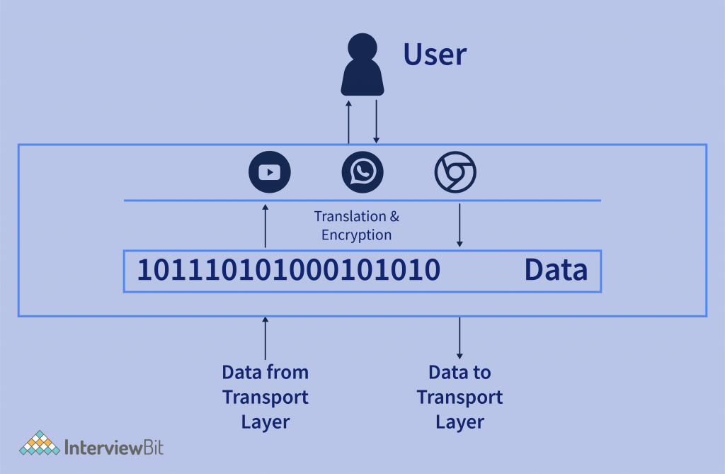
- In the above figure, the data that came from the end-user application is being converted to binary data for the next layer for further processing. And on another side, the data that came from the presentation layer is converted into user-readable application data.
Transport layer
The transport layer enables communication between two processes. It ensures that the data to be sent to the destination must de be delivered to the same process that it has been
The transport layer enables communication between two processes. It ensures that the data to be sent to the destination must de be delivered to the same process that it has been meant for.
Processes are nothing but the application that is requesting or sending data. Each process communicates with the port number that helps the transport layer to identify the correct process meant for the data.
In transport Layer, It has majorly two protocols. TCP (Transmission Control Protocol) and UDP (User Datagram Protocol).
Explanation – In the image, we can see that Post Sender belongs to a process that is occupied by the Application in the sender system to send the data, And on the other side Port receiver belongs to the Application process. So transport layer ensures that the data must deliver to the correct application.
Transport Layer performs the following operation on the bits of data received from the Application layer. And those are –
- Segmentation – Segments are the small groups of data that are divided from the large data. Suppose we have 10 MB of data then the whole 10MB data is divided into segments supposing 1MB each.
Here Data Can be considered as the sequence of bytes that is received from the above layer.
These segments are sent to the lower level for further process.
Why Segmentation? – The big question arrives is why the data is divided into segments? Why can’t the whole lot is being sent on a go?
- It is because the packet size of (TCP or UDP) has some limitations with the size of packet defined by IEEE.
- Segmentation does that if the data is divided into pieces, then it is more manageable.
- Each segment must be given a number because, in transportation, It may not the situation that the segment arrives in the same sequence.
- On the other end in Transport Layer, If a segment has a number then it will be easy to send the data over the medium.
- Each Segment contains the port number that needs to identify the hat software did access this data that is sent to the network.
- A general segment looks like –

2. Flow Control – Flow control means managing the flow of data that is transmitted between one host to another host.
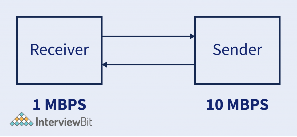
- Supposed Sender is sending data to Reciever @10MBPS Transfer Rate. But Reciever can’t able to process the data @10MBPS. It can only process data @1MBPS.
- So receiver will ask the server for a 1MBPS Transfer rate, As it can’t process the data. Then sender sends the data @1MBPS Rate.
- So this is called Flow Control.
3. Error Control – It controls the error of data. This means in case there is any inconsistency happened on the data then it helps to correct that data.

- Suppose Sender is sending some data considering 4 segments. Now in case, the 3rd segment got lost in the medium. So Error control helps to fix that.
- It has some algorithms that help to fix this data. Like Automatic Repeat Request. In which the segment which hasn’t receiver to the receiver. Then it will ask to resend it.
- Data loss can happen in the physical network, So errors are recognized controlled by the transport layer.
We have encountered a word called TCP and UDP. These are the protocols that describe the type of packets that are generated by the transport layer for each segment it has been divided.
| TCP | UDP |
|---|---|
| Transmission Control Protocol (TCP) is one of the main protocols of the Internet Protocol Suite. It is mostly used for webpage transmission. | User Datagram Protocol (UDP) is also one of the most used protocols on the Internet. UDP protocols are used in many where connection orientation is not the main priority and want faster data transmission. And some loss of data is acceptable. |
| The most essential feature of TCP is – 1. It is a connection-oriented protocol. 2. It provides feedback once the packet is successfully received on the other end and that makes TCP a slower protocol. 3. There can be no loss of data can happen in TCP. | The most essential feature of UDP is – 1. It is a connection-less protocol. 2. It transmits the data faster, but there can be a loss of data. 3. No Feedback mechanism is used in this. |
The above figure describes a very high-level overview of what happens in the Transport Layer. The Header need not be each time TCP or UDP. It can be more like ICMP (Internet Control Message Protocol), DNS (Domain Name System), ARP (Address Resolution Protocol), etc. depending on the type of data or request.
Network Layer
Whatever data comes from the above layers in the form of segments that data are encapsulated with the Source and Destination I.P. Address that we call as packet, and these packets are sent to the network it belongs to.
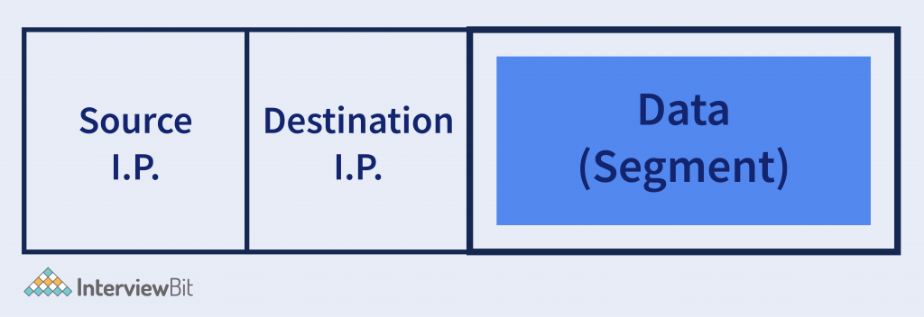
IP Address helps to identify the network to which the packet has to be sent. There is a very famous protocol used in the Network layer, called IP (Internet Protocol). IP has two different versions that have been widely used nowadays.
- IPv4 (Internet Protocol version 4).
- IPv4 (Internet Protocol version 6).
What is IP Address? It is the address that the network system has uniquely identified. It is the 32-bit or 4-byte address (in IPv4) and each byte has an address range of 0-255, called an octet. And in (IPv6) it is 128bit long with 16 octets in it.
What does IP Address do? In the real world, there are billions of devices are connected to the internet. And these devices are spread all across the globe. So the device is difficult so the IP Address provides that it groups the devices into a particular network with the unique IP Address, which helps to identify where the device is to whom the communication to happen.
IPv4 – It is the internet protocol version 4 address assigned to the device that connects to the network for identification. It is 32-bit long which means the number of devices it can connect is up to – 232-2.
It has a header of 20 Octets (Bytes) in which the data from the transport layer is encapsulated. And this header helps to identify the packet and which network it belongs to.
IPv6 – It is the Internet Protocol version 6 address assigned to the device that connects to the network for identification. It is 128-bit long. So the number of devices it can connect to is 2128 – 2.
It also has a header of 40 Octets (Bytes) that contains that helps to identify the packet and the network it belongs to.
Modern Routers works on this network layer as the packets need to be routed from the source to the destination.
What is Routing? Routing means setting the path of the packet to reach from the sender to the receiver.
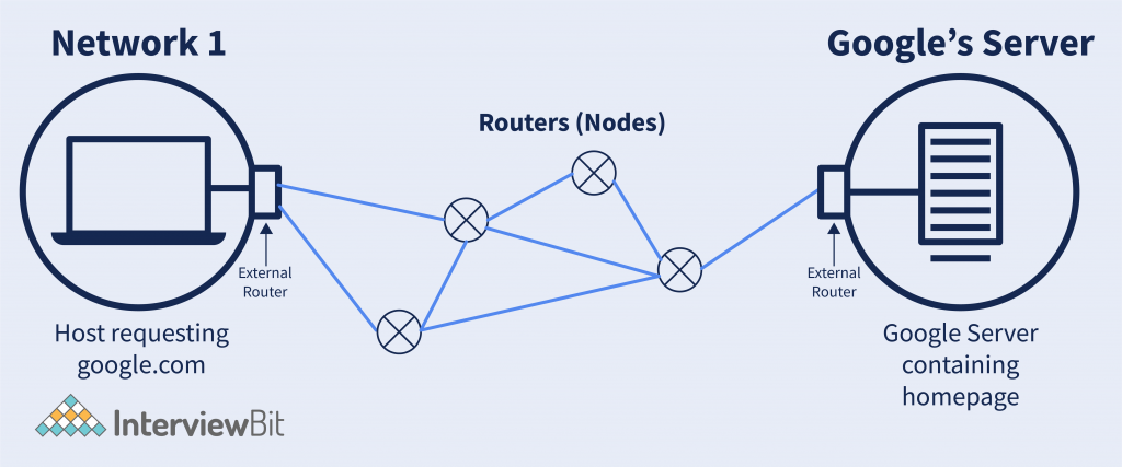
Explanation – Suppose we visit the website google. Then google’s network has theirs in US California. So what will happen here is, the packet sent from the host to the google server will have to follow some path. Because there might be no direct connection from the host to google’s server. And between paths, there can be many routers present. So setting, what will be the next router through which the packet needs to be transmitted, and the connection between these is called Routing. And the router handles these things.
There is an external router associated with the network that deals with sending the packet from the host network to the destination network using the next node.
How do routers do that? The router does this, When a router gets the destination IP address then performs something called masking.
Masking is a simple bitwise operation. The router sets some bits to 0 and performs a bitwise AND operation, and after masking on the destination IP address, it will get the network IP Address.
Now with the help of the network IP address, it will decide the next router for the packet it has to send.
How to network layer encapsulate the packet with the IP Address? There is something called DNS. Domain Name System, that provides the IP address corresponding to the domain name it has been requested for.
Path Determination – What it means is actually what, there could be multiple ways from which I can send one packet to the destination. The objective of path determination is to determine the best path so that I can send this packet very very efficiently in less time.
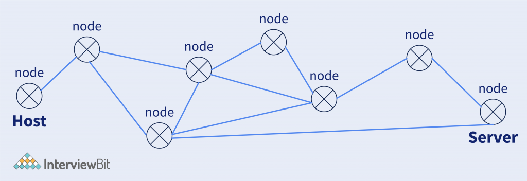
So here in the above figure, we have multiple nodes from the host to the server. So routers help to determine the path that needs to be followed so the packet reaches the destination efficiently.
So routers use algorithms used in graph theory, like minimum spanning tree, shortest path, etc.
Data Link Layer
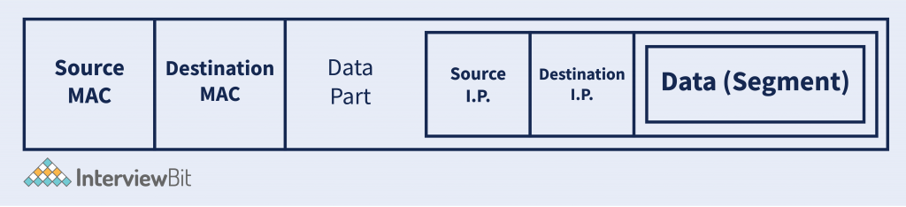
The packet is sent from the Network layer, And on that packet the headers are added along with the MAC Address of Source and Destination.
- MAC Address – (Media Access Control) also called physical address, is the 48-bit or 6-Bytes long containing the Hexadecimal code. It is the address assigned uniquely to each of the network devices. NIC(Network Interface Card) WiFi Card, USB WiFi Dongle, etc.
After encapsulating the packet from the network layer with the Source and Destination MAC Adress. Data-Link Layer generates a Frame. And that frame is sent to the next layer for data to send to the destination. A general frame looks like –
Why MAC Address? MAC address helps to uniquely identify the device. Suppose in the network, the packet is received, then which particular device belongs to. So the MAC address helps to identify this.
We have seen in the network layer that IP Address is used to uniquely identify the device and MAC Address also performs the same. So why not only use either MAC Address or IP Address?
MAC Address is uniquely assigned to every single device that is connected with the network. And there are even billions of devices on the internet actress the globe. So if any host wants to send the data from one location to another, then without knowing the location, how it can reach. So IP Address behaves the same, IP address is the logical address that defines a particular location of network it belongs to. And after breaching the location of the network the MAC Address helps to identify the device. And that is what happens in the Data-Link layer, which defines the end device that the packet belongs to.
Example – 1 Letter needs to be sent From INDIA to the US. So The destination Address contains – Country Name -> State -> City Name -> Pin Code -> Street -> Home Address.
Here it is forming a hierarchy, That is exactly what IP Address helps to recognize the destination. (Up to the Street). And after reaching the street the Home Address is identified. And that MAC Adress helps to do.
On the other hand, Data-Link Layer also has some broadcast –
- Access to Media – Media are like – (Copper Wire, Fiber Optical Cable, Wireless), etc. So the data link layer has access to these media on which medium the packet needs to transfer. Access to the media can help to detect congestion, Error, Collision, etc.
- Media Access Control – Data Link Layer has control over the data, which means when to transmit the data, Is there any error while transmitting? Is Data received is error-free? etc.
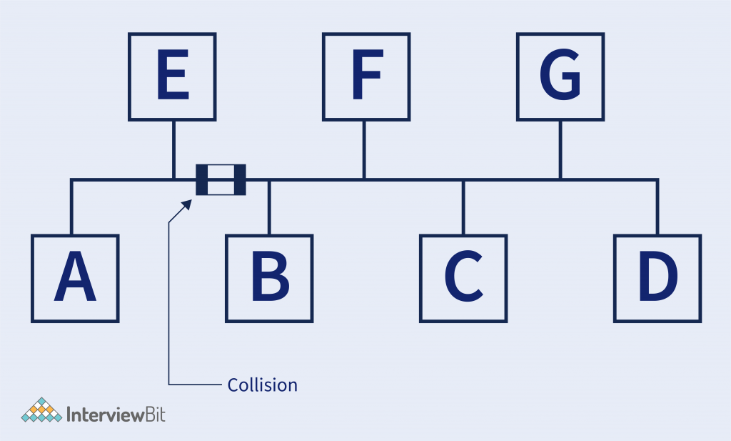
- Example – Suppose there are several hosts connected in the same medium, Consider in (BUS TOPOLOGY).
- In the below figure, Host B is sending data to Host A, and at the same time, Host E is also sending some data to Host C. So there is a collision. In the end, it is the electrical pulses that travel on the medium, and that will collide the whole data.
- So Data Link-Layer has access to the medium and there are a bunch of algorithms used for detecting avoiding the collision. Like CDMA, TDMA, CSMA – CD, etc.
- Error Detection and Correction – It is the mechanism to detect any error on the data. This means checking whether the data is correctly received or not.
- Some algorithms help to check that. Like – CRC (Cyclic redundancy check), Checksum, Bit Parity, etc.
- And these works like a function on which input is given and it returns some bits that are piggybacked with data and on the destination, that bit helps to detect the error.
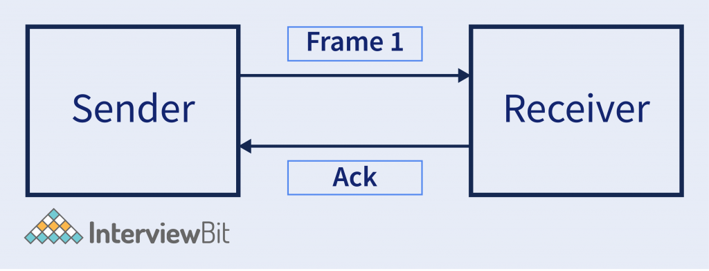
- Optional – It also has some other operations like Flow Control & Acknowledgement. Acknowledgment – It means informing the sender that the frame it has sent is successfully received by the receiver.
- Flow Control – It is a set of procedures that explain to the sender how much data or frames it can transfer or transmit before data overwhelms the receiver. The receiving device also contains only a limited amount of speed and memory to store data. So, informing the sender that stops sending frame after some certain number of frames.
- The below image is the high-level view of how data is encapsulated with the IP Address in the Data-Link layer.

Physical Layer
Physical Layer deals with the signals, that how data to transmit to the medium. From the Data-Link layer, the frame of bits received then is sent converted into the actual electrical signals according to the type of medium is used. Like Light beam signal for Optical Fiber Cable, Radio Frequency for wireless. Etc.
There are many encoding schemes in which the data is encoded. Like – Manchester Encoding (As per G.E. Thomson and also IEEE 802.3 Encoding Scheme), Differential Manchester Encoding Scheme. Etc
Other, on the receiver side, the physical layer accepts the electrical signal that is received, Decodes that signal and makes to a stream of bits, and sends it to the upper layer (Data Link Layer).
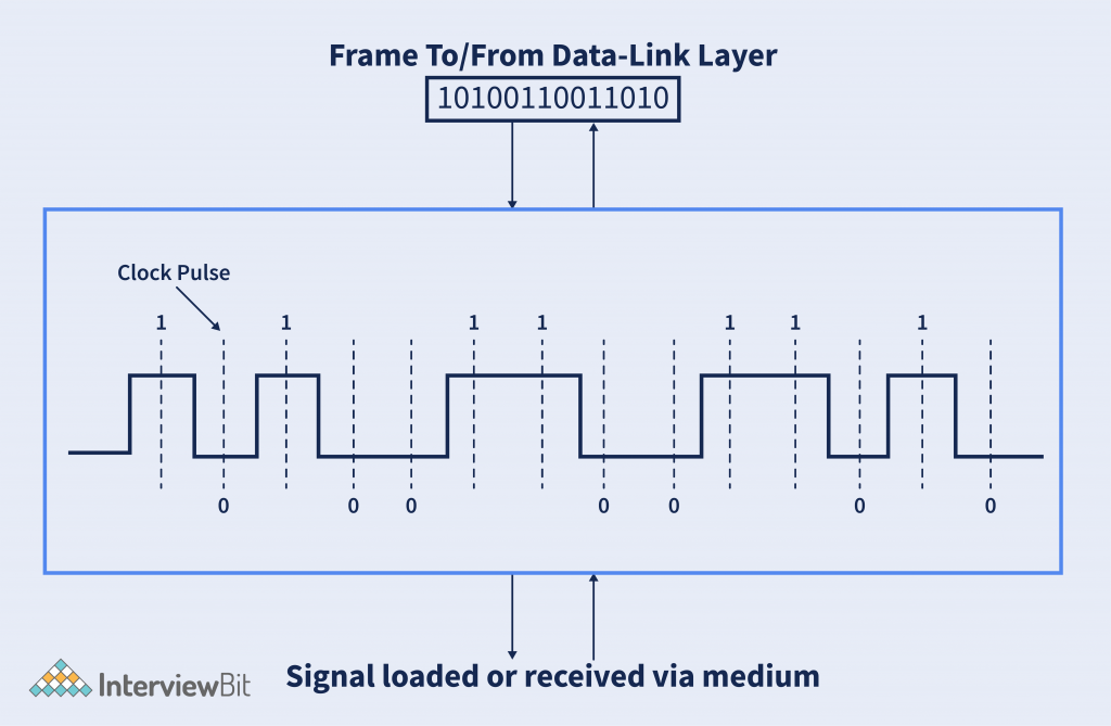
The above image shows the frame received from the data-link layer is converted into the electrical signals and loaded to the medium.
High-Level Diagramatic Overview of Data flow from the User application to the medium in TCP/IP Model –
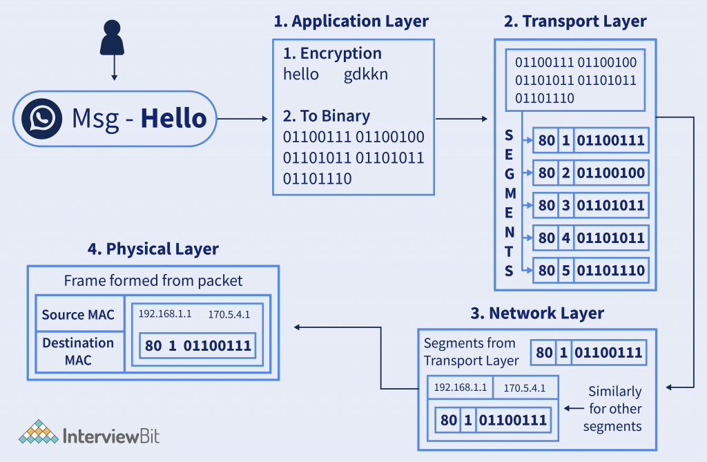
Steps Explained –
- Suppose users send messages on WhatsApp – “Hello”. Then on the application layer, it is encrypted according to the algorithm. And them the ASCII or UNICODE text is converted to binary data and sent to the next layer.
- In the Transport layer, the data is divided into segments and sent to the next layer for processing.
- In the network layer, the source and destination IP Address is added and forms a packet of each segment, and sent for the next layer.
- In the Physical Layer, the MAC address of the destination is added and the frame is converted into signals and the bitstream is loaded to the medium, and then it transmits to the network to reach the destination.
Conclusion
TCP/IP model is the practice used model, consisting of a bunch of protocols for the successful transmission of data, from source to the destination. It takes reference from the OSI model to implement it in the real world.
TCP/IP Model is reliable and fast as it contains a bunch of protocols that help to achieve this task. TCP/IP model acts as the foundation of the Internet. Because after the model applied by the US DoD for its communication, they called it ARPANET that is used only for US Military. And after it becomes a public network, the name given the INTERNET (International network). The backend of the whole internet has the TCP/IP Model.